How EV powertrain components in Europe are adapting to 800V systems




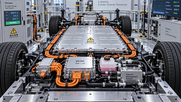
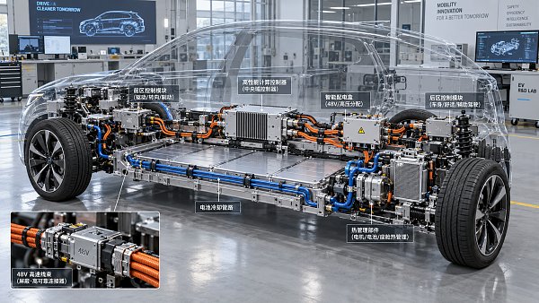
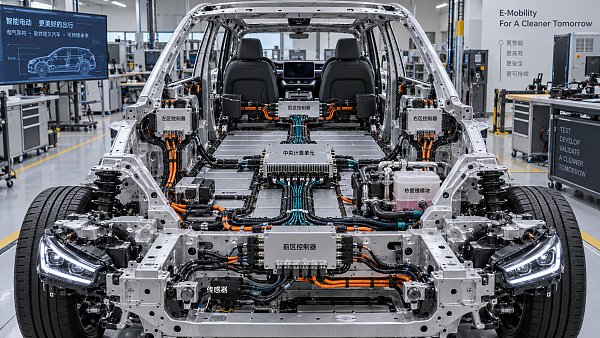
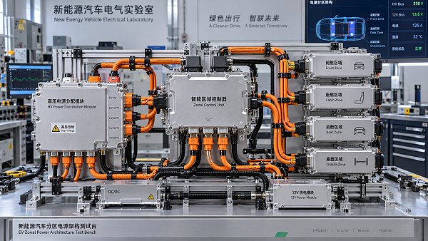
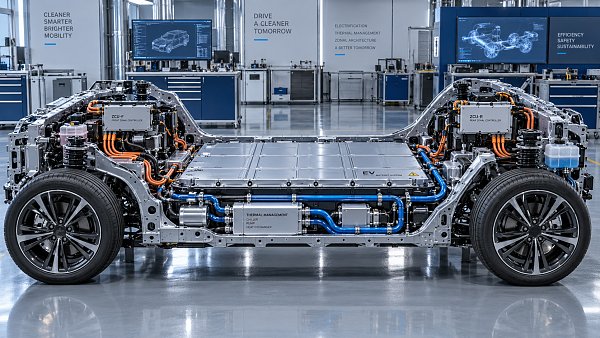
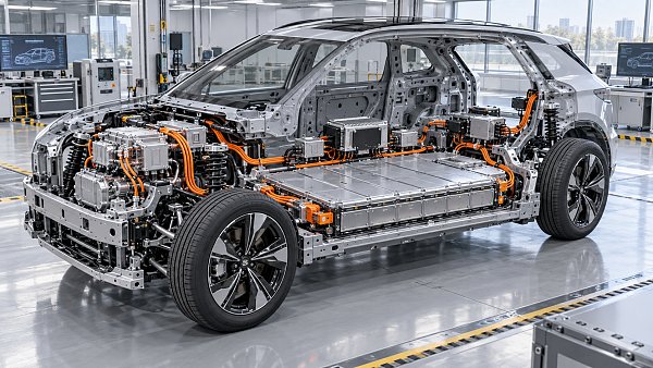
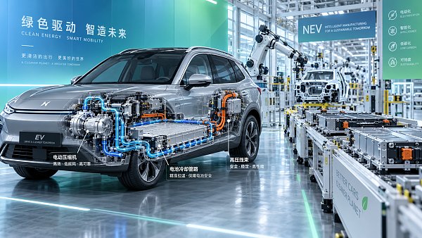
Europe’s move toward 800V electric vehicle architectures is changing the design brief for powertrain components well beyond a higher nameplate voltage. The attraction is clear: higher voltage allows the same power to be transferred with lower current, which can reduce resistive losses and ease conductor mass. Yet the benefit only appears when the inverter, e-motor, e-axle, battery interface, high-voltage harness, connector system, and cooling circuit are developed as a coordinated electrical and thermal system.
For EV powertrain components in Europe, the transition is uneven. Some vehicle programs use 800V capability mainly to shorten high-power DC charging events, while others use it to raise continuous power density in performance-oriented or heavy-duty applications. A component that works acceptably during a short charging peak may face very different stress in a compact e-axle delivering repeated high torque on mountain roads, motorway cruising, or towing duty. Voltage class alone therefore says little about field readiness.
Higher voltage shifts the weakest-link problem
At a given power level, an 800V system carries roughly half the current of a comparable 400V system. This changes several familiar constraints. Copper cross-section can be reduced in selected cables and busbars, I2R losses fall, and charging equipment can transfer substantial power without pushing current to the same level. However, electrical stress across insulation, semiconductor switching nodes, connector interfaces, and parasitic capacitances rises.
The resulting engineering question is not whether every part is rated above 800V. It is whether the complete path retains adequate dielectric strength, thermal margin, partial-discharge resistance, electromagnetic compatibility, and service-life stability after assembly and ageing. A nominal voltage value does not capture transient overshoot from inverter switching, charging events, fault interruption, or load changes. The local voltage at a motor terminal can differ materially from the battery-side voltage because cable inductance and fast switching edges create reflections.
This is why European 800V programs are placing greater attention on interface definitions. The inverter, motor winding system, phase cable, shield connection, connector geometry, coolant routing, and control software cannot be reviewed as isolated catalog items. Small mismatches at their interfaces can create excessive heat, common-mode current, insulation damage, or measurement errors that do not appear in basic bench tests.
Inverters are moving toward faster switching with tighter thermal control
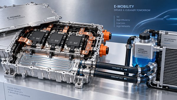
The inverter remains one of the clearest indicators of 800V maturity. Silicon carbide power devices are increasingly considered where high-voltage operation, switching efficiency, and compact cooling requirements justify their use. Their value is not simply lower conduction loss. Faster switching can reduce losses in certain operating regions and support smaller passive components, but it also creates steeper voltage transitions. Those transitions place more pressure on motor insulation, cable shielding, bearing-current control, and electromagnetic design.
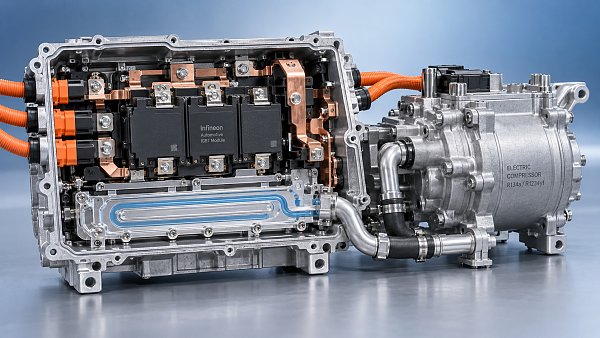
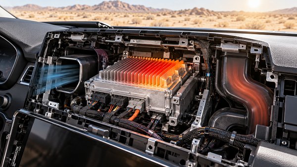
A low-loss inverter module can still become a system problem if thermal paths are poorly defined. Semiconductor junction temperature depends on more than coolant inlet temperature. Contact pressure, thermal interface material spread, baseplate flatness, coolant plate geometry, flow distribution, and air retention in the circuit all affect the temperature gradient from chip to coolant. A cooling plate that performs well in a steady-state thermal test may behave differently during rapid acceleration and regenerative braking, when heat generation changes faster than coolant temperatures stabilize.
European vehicle packaging also encourages compact, integrated drive units. This can shorten electrical paths and simplify assembly, but it concentrates heat sources. Inverter power modules, gate drivers, DC-link capacitors, reduction gears, and electric motors may share a housing or closely coupled cooling circuit. The trade-off is clear: less volume and fewer external connections can improve packaging, while repair access, thermal isolation, vibration transfer, and leak containment become harder to manage.
DC-link capacitor selection deserves particular attention. Voltage rating alone is insufficient. Ripple current, equivalent series resistance, high-frequency behavior, operating temperature, mechanical fixation, and expected voltage transients determine whether the capacitor remains stable through the vehicle life. A design with adequate capacitance but poor high-frequency layout can expose the switching devices to unwanted overshoot, forcing later changes in snubber design, busbar geometry, or inverter control calibration.
E-axles need insulation systems designed for inverter behavior
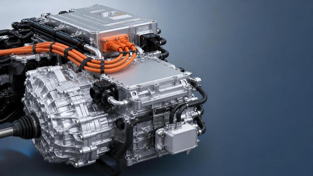
In an 800V e-axle, the motor is not exposed only to the battery voltage. Pulse-width modulation from the inverter produces repetitive high-frequency voltage stress at the winding terminals. The insulation challenge is therefore connected to rise time, cable length, winding geometry, slot liner material, impregnation quality, and the presence of microscopic voids. Voids can become sites for partial discharge under certain electrical and thermal conditions, progressively weakening insulation even when conventional resistance measurements appear acceptable.
Hairpin windings are widely used to raise copper fill factor and support automated production, but they bring their own process sensitivities. Edge preparation, enamel integrity after bending, weld-zone cleanliness, and resin penetration all matter. A process that leaves minor coating damage or incomplete impregnation may pass early electrical tests yet lose margin after thermal cycling and vibration. The issue is especially relevant where compact windings operate at elevated temperature near high switching-frequency inverters.
Motor bearing current is another area where similar symptoms can have different causes. Electrical pitting may stem from common-mode voltage, inadequate shaft grounding, bearing lubrication condition, grounding-path variation, or an unsuitable shielding termination. Replacing the bearing without identifying the current path can lead to repeat failures. Insulated bearings, conductive brushes, shaft grounding rings, and revised inverter filtering address different mechanisms; they are not interchangeable fixes.
Motor cables deserve the same scrutiny. A phase cable selected only by current capacity may have unsuitable insulation thickness, screen construction, flexibility, or termination geometry for the switching environment. The shield must be continuous enough to control emissions and common-mode behavior, while its grounding arrangement must match the e-axle and inverter housing strategy. A screen connection that is electrically sound on a bench can become inconsistent after vibration, corrosion exposure, or repeated service disconnection.
Harnesses and connectors are becoming electro-thermal assemblies
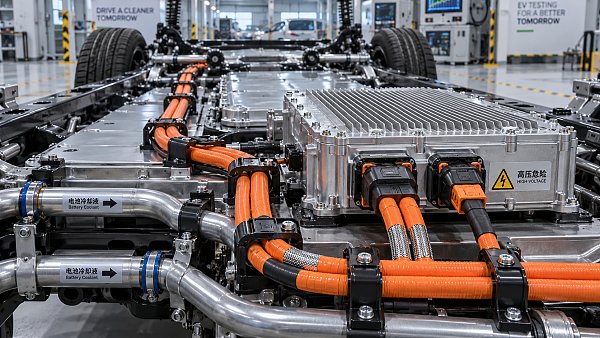
Lower current can reduce the mass of some high-voltage harnesses, but it does not eliminate their design difficulty. At 800V, creepage and clearance requirements, insulation aging, sealing, connector touch protection, and high-voltage interlock integrity become more sensitive to packaging. Underbody routing introduces water, salt, stone impact, temperature cycling, and movement between body-mounted and powertrain-mounted components. A cable’s laboratory bend radius says little about its durability if the installed routing imposes repeated torsion at a sealed connector.
Connector heating remains localized. The overall cable may run cool while a terminal interface develops a high-resistance hot spot because crimp geometry, plating condition, terminal spring force, or assembly cleanliness has drifted. This becomes harder to detect when current is lower than in a 400V equivalent, because the system may remain functional until a transient load or elevated ambient temperature exposes the weak connection. Contact-resistance monitoring, cross-section inspection, crimp-force process control, and post-assembly retention checks all carry more weight than a simple pass/fail continuity result.
Service disconnects, contactors, fuses, and pyrotechnic isolation devices must also be reviewed as a fault-management chain. Interrupting DC at higher voltage differs from opening an ordinary low-voltage circuit because arc behavior, opening speed, current direction, and fault energy influence the outcome. A protective device has to be matched to the battery pack’s short-circuit behavior and the vehicle’s control logic, rather than selected by voltage and continuous current values alone.
Thermal systems are being asked to protect both charging speed and component life
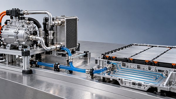
800V capability is often associated with rapid charging, but charging performance depends on battery temperature, cell impedance, cooling distribution, connector temperature, charger communication, and pack control strategy. The powertrain thermal circuit must avoid treating the inverter, motor, gearbox, battery, and cabin system as unrelated loads. Their thermal demands overlap but are not identical.
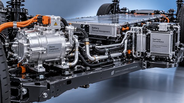
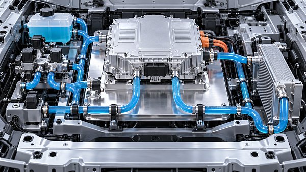
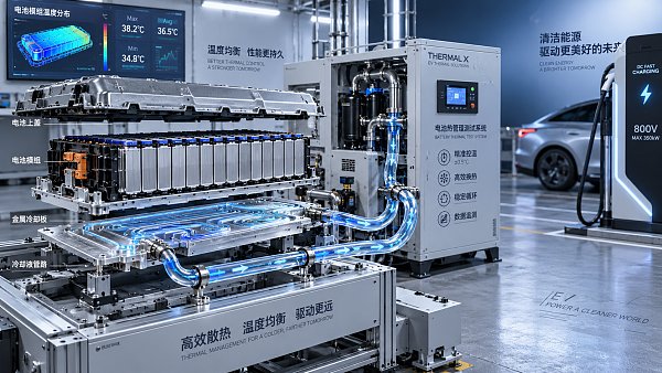
Battery cooling generally seeks relatively uniform cell temperatures, while an inverter may tolerate a different coolant temperature range if junction temperatures remain controlled. A motor and reduction gear introduce still another requirement because winding hotspots and lubricant behavior do not follow the same thermal profile. Integrated thermal valves and multi-branch coolant circuits can direct flow where it is needed, but the control logic must account for pressure drop, pump capability, valve response time, trapped air, and cold-weather viscosity.
A common misreading is to judge a cooling design by peak heat-rejection capacity alone. Flow maldistribution can leave one inverter region or a group of battery cells warmer than the average. Similarly, a large heat exchanger does not solve a local thermal-interface problem inside a power module. Component-level temperature sensing, model-based estimation, and carefully placed coolant sensors are needed to distinguish insufficient system capacity from poor heat transfer at a specific interface.
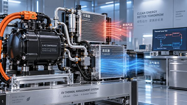
Heat-pump integration adds another layer. Using available waste heat may improve overall energy use in cool weather, yet the thermal system needs enough control authority to prioritize battery conditioning before high-power charging or sustained high-load driving. Valve sequencing that is acceptable during gentle urban operation can create unwanted temperature swings during a charging stop followed immediately by motorway driving.
Validation is moving from component compliance to coupled stress testing
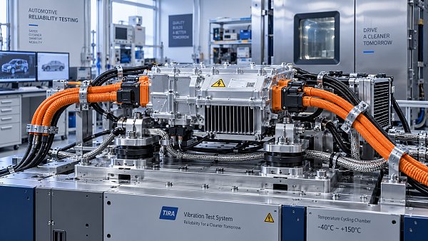
The most consequential changes are appearing in validation plans. Separate electrical, thermal, vibration, sealing, and electromagnetic tests remain necessary, but they can miss failures created by combined stress. An e-axle may pass vibration testing at room temperature and pass dielectric testing in a static fixture, then show insulation weakness only after hot coolant exposure, vibration, humidity cycling, and high-frequency inverter operation are combined.
Several observations provide stronger evidence of readiness than a voltage label:
- Waveforms at the motor terminals, including overshoot and ringing, reveal whether the inverter-cable-motor combination is imposing stress beyond the intended insulation design.
- Thermal maps under repeated acceleration, regeneration, and charging transitions show whether a compact assembly has local hotspots hidden by average coolant temperature.
- Insulation resistance is useful, but partial-discharge screening and ageing behavior provide a more relevant view where fast switching and high electric field concentration are present.
- Harness and connector validation should include installed geometry, strain relief, shield termination, environmental exposure, and realistic mating cycles rather than loose-component testing alone.
- End-of-line tests need process sensitivity. Detecting a gross short circuit is different from detecting a marginal crimp, incomplete resin fill, displaced gasket, or unstable thermal interface.
Manufacturing variation becomes more visible as design margins narrow. Busbar alignment, laser-weld consistency, potting compound cure, connector seating, coolant plate sealing, and torque control can all change electrical or thermal performance. Traceability is valuable when it links a failure signature to a defined process condition rather than merely recording serial numbers. This is particularly relevant for integrated drive units, where disassembly may be limited and root-cause access becomes expensive after final vehicle installation.
European sourcing decisions are increasingly shaped by integration evidence
The market is not moving toward a single universal 800V component set. Premium passenger vehicles, compact vehicles, performance applications, commercial platforms, and regional charging conditions create different trade-offs. A high-voltage harness optimized for mass may be unsuitable for a route with frequent abrasive movement. A very compact silicon carbide inverter may require cooling quality that a lower-cost platform cannot maintain. An integrated e-axle can reduce external interfaces while making replacement strategy and fault isolation more restrictive.
Component comparisons are strongest when they connect rated values to the actual operating envelope: battery maximum voltage, switching frequency, cable length, coolant condition, ambient exposure, peak duration, continuous load, service access, and expected manufacturing process capability. This avoids the recurring error of treating “800V-ready” as a complete technical description.
Europe’s 800V transition is therefore pushing EV powertrain development toward tighter electrical, thermal, and mechanical coordination. The components adapting most successfully are those whose material choices, interfaces, validation methods, and production controls were developed around the behavior of the complete high-voltage system.
Related News
- 00
0000-00
How electric compressor speed affects EV battery cooling capacity - 00
0000-00
How to verify a variable frequency compressor supplier’s efficiency claims - 00
0000-00
How bend radius affects FPC reliability in automotive camera modules - 00
0000-00
How to diagnose intermittent loss of electric power steering assist - 00
0000-00
How to size automotive power modules for electric compressors
Weekly Insights
Stay ahead with our curated technology reports delivered every Monday.
Recommended News
 How electric compressor speed affects EV battery cooling capacityElectric compressor technology: battery cooling depends on more than RPM. Discover how speed, refrigerant flow, and system limits affect EV cooling capacity and energy efficiency.Author:Time:Oct 19, 2026
 How to verify a variable frequency compressor supplier’s efficiency claimsVerify a variable frequency compressor supplier’s efficiency claims using COP boundaries, matched test conditions, and duty-cycle data. Learn how to choose with confidence.Author:Time:Oct 18, 2026
 How bend radius affects FPC reliability in automotive camera modulesAutomotive FPC applications: camera module reliability starts with bend radius. Learn how stack-up, strain, and validation guide robust designs and help prevent costly failures.Author:Time:Oct 17, 2026
 How to diagnose intermittent loss of electric power steering assistMaster power steering system diagnostics to trace intermittent EPS assist loss. Learn proven checks for voltage, wiring, and fault codes to avoid costly guesswork.Author:Time:Oct 16, 2026
 How to size automotive power modules for electric compressorsSize automotive power modules for electric compressors with confidence. Learn how voltage, phase current, losses, and cooling shape reliable selection—and avoid costly oversizing.Author:Time:Oct 15, 2026
 Why automotive power electronics are shifting to silicon carbideAutomotive Power Electronics are shifting to silicon carbide. Discover how SiC can cut losses, boost EV power density, and reshape cooling, reliability, and system costs.Author:Time:Oct 14, 2026
 How EV adoption shapes the electrically driven compressor marketExplore how EV adoption shapes the electrically driven compressor market, from battery cooling and heat pumps to supplier margins. Discover the drivers of profitable growth.Author:Time:Oct 13, 2026
 How to size a PTC heater for reliable EV cabin heatingPTC Heater sizing for EV cabins: learn how to balance defrost performance, heat-pump integration, airflow, voltage range, and battery power for reliable winter comfort.Author:Time:Oct 12, 2026
 What determines the cooling output of electric automotive AC compressors?Automotive air conditioning compressors electric systems: explore how speed, voltage, refrigerant, controls, and heat exchangers shape EV cooling capacity and efficiency.Author:Time:Oct 11, 2026
 What makes a touchscreen media head unit responsive enough for daily use?Touchscreen media head unit performance explained: discover what delivers fast starts, smooth maps, reliable phone pairing, and responsive daily driving.Author:Time:Oct 10, 2026
 Can a Domain Controller Share a Cooling Loop with Other Electronics?Can a domain controller share a cooling loop with other electronics? Explore thermal zoning, flow control, safety priorities, and reliable vehicle electronics cooling strategies.Author:Time:Oct 19, 2026
 What Causes Domain Controller Overheating During Summer Testing?What causes domain controller overheating in summer testing? Explore heat load, airflow, installation, software factors, and practical fixes.Author:Time:Oct 18, 2026
 Is a Head-Up Display Hard to Integrate with Different Windshields?Is a head-up display difficult to integrate with different windshields? Discover how glass geometry, coatings, and calibration affect HUD clarity, cost, and production readiness.Author:Time:Oct 17, 2026
 What Should Be Checked Before Selecting an Automotive Head Unit?What should be checked before selecting an automotive head unit? Explore compatibility, performance, cybersecurity, compliance, and supplier support.Author:Time:Oct 16, 2026
 Is Steer-by-Wire More Expensive Than an EPS Steering System?Is steer-by-wire more expensive than an EPS steering system? Explore the true costs, safety demands, software value, and when SbW justifies its premium.Author:Time:Oct 15, 2026
 Which Automotive Electronics Need Validation for 800V Platforms?What automotive electronics should be validated for 800V platforms? Explore critical checks for harnesses, power electronics, thermal systems, safety, and EMC.Author:Time:Oct 14, 2026
 How Do Automotive Compressor Export Requirements Vary by Market?How do automotive compressor export requirements vary by market? Explore key compliance rules for refrigerants, EV safety, OEM approvals, labeling, and customs.Author:Time:Oct 13, 2026
 What Documents Are Needed to Export Automotive Thermal Components?What documents are needed to export automotive thermal components? Explore customs, compliance, technical records, and shipping tips to prevent costly delays.Author:Time:Oct 12, 2026
 How Often Should an EV Air Conditioning Compressor Be Inspected?How often should an EV air conditioning compressor be inspected? Discover recommended service intervals, warning signs, and expert care tips to protect cooling performance and EV reliability.Author:Time:Oct 11, 2026
 How to size power solutions for automotive head-up display systemsHeads-up display systems power solutions: learn how to size automotive HUD power architectures for startup, brightness, thermal limits, EMC, protection, and reliable vehicle operation.Author:Time:Oct 19, 2026
 How does a head-up display work in a high-performance car?Hoe werkt een head-up display in een high-performance auto en welke informatie toont het? Discover the tech, safety alerts, and performance data that sharpen every drive.Author:Time:Oct 18, 2026
 Which trends will shape zonal EV architectures in the next decade?Future trends in zonal EV architectures: explore smarter power distribution, 48V systems, thermal integration, software, and resilient networks shaping next-gen vehicles.Author:Time:Oct 17, 2026
 When does a zonal EV architecture outperform a centralized design?Explore the trade-offs between zonal and centralized EV architectures to identify the best path for harness efficiency, software scalability, safety, and faster EV launches.Author:Time:Oct 16, 2026
 How to compare vendors for zonal EV power architecturesComparing vendors for zonal EV power architectures: assess electrical capability, interface ownership, lifecycle support, and integration risk for smarter sourcing.Author:Time:Oct 15, 2026
 How zonal architectures can improve EV reliability at the system levelHow zonal architectures affect EV reliability: explore fault containment, diagnostics, power resilience, and software strategies for more dependable electric vehicles.Author:Time:Oct 14, 2026
 What is driving growth in the automotive E/E architecture market?Explore what drives the automotive electric electronic systems architecture market, from EV power systems and zonal computing to ADAS, cybersecurity, and software-defined vehicles.Author:Time:Oct 13, 2026
 How to evaluate top-rated vehicle electrical components for reliabilityDiscover how to evaluate top-rated vehicle electrical components for reliability, from connector integrity and thermal margins to validation data and manufacturing control.Author:Time:Oct 12, 2026
 What makes vehicle electrical components reliable over a long service life?Top-rated vehicle electrical components for reliability depend on thermal control, sealing, vibration resistance, and validated manufacturing. Discover how to choose durable parts.Author:Time:Oct 11, 2026
 How battery thermal management solutions prevent fast-charge overheatingBattery thermal management solutions prevent fast-charge overheating with intelligent cooling, valve control, predictive preconditioning, and reliable heat rejection.Author:Time:Oct 09, 2026
 What an automotive market report can reveal about EV demand shiftsAutomotive market report insights reveal EV demand shifts, component opportunities, regional risks, and smarter investment strategies for growth.Author:Time:Oct 08, 2026