How to evaluate top-rated vehicle electrical components for reliability




A component can be highly rated and still be the wrong reliability choice for a vehicle program. Ratings often compress several different attributes into one label: warranty history, perceived brand quality, catalog coverage, or a favorable result in one operating environment. Technical evaluators need to separate those signals from evidence that the component will remain electrically stable, mechanically intact, and diagnostically manageable over its intended life.
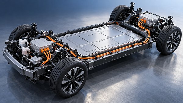
For vehicle electrical systems, reliability is a system property. A high-voltage harness depends on conductor sizing, shielding, terminals, seals, routing, and mating interfaces. A cockpit display or media head unit depends on power conditioning, thermal design, software behavior, electromagnetic compatibility, and the durability of its connectors. The first question is therefore not which part is “top-rated,” but whether its validation evidence matches the electrical, thermal, vibration, environmental, and service conditions of the target vehicle.
Start with the failure consequences, not the catalog ranking
Component criticality should determine the depth of evaluation. A failure in an accessory USB cable and a failure in a high-voltage interlock loop do not deserve the same evidence threshold. Likewise, an intermittent communication cable in a smart cockpit may create a customer-facing defect, while an intermittent sensor or steering-related electrical connection may affect controllability or trigger a degraded operating mode.
A practical review begins by placing the component in its vehicle context:
- Safety or propulsion relevance: Could loss of continuity, insulation degradation, voltage drop, or a corrupted signal affect traction, braking, steering assistance, thermal protection, or high-voltage isolation?
- Operating duty: Is the part continuously energized, subject to repeated high current, exposed to compressor-induced vibration, or used only intermittently?
- Installation location: Underhood, underbody, battery pack, door, instrument panel, roof, and cabin locations impose very different combinations of heat, moisture, salt exposure, movement, and electromagnetic noise.
- Serviceability: Can the part be replaced without major disassembly, or would a minor connector failure require extensive labor or replacement of a larger assembly?
- Fault tolerance: Is there redundancy, diagnostic coverage, derating, or a safe fallback function when the component drifts out of specification?
This step prevents a common purchasing mistake: applying the same supplier scorecard and acceptance logic to every electrical item. A lower-cost alternative may be acceptable for a contained, easily serviced application. It is far harder to justify where access is poor, failure diagnosis is ambiguous, or the circuit supports a high-consequence function.
Read electrical specifications as operating limits
Nominal voltage, current rating, and connector pin count are necessary starting points, but they rarely establish reliability on their own. Ratings need to be interpreted against the application’s peaks, transients, temperature rise, duty cycle, and expected aging.
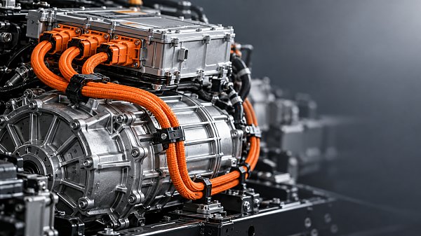
For power distribution, harnesses, terminals, relays, and electric compressors, examine the full current profile rather than only steady-state load. Repeated inrush events, switching transients, charging loads, motor start conditions, and elevated ambient temperature can accelerate contact wear and raise conductor resistance. A terminal that is acceptable at room temperature under a short bench test may operate much closer to its margin in a crowded power electronics or HVAC installation.
For data and communication cables, reliability includes signal integrity after installation and aging. Evaluate impedance control where applicable, shielding construction, grounding strategy, connector retention, bend-radius limits, and routing sensitivity to nearby high-voltage or switching sources. A cable assembly can pass a standalone continuity check yet produce intermittent communication faults after vibration, clamp loading, or thermal movement changes the shield or contact interface.
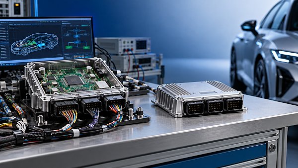
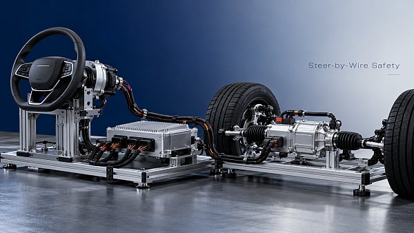
Electronic control units, displays, head units, HUD modules, and steer-by-wire-related electronics require a broader electrical review. Input-voltage tolerance, reverse-polarity protection, load-dump resilience, wake/sleep behavior, brownout recovery, and electromagnetic immunity should be understood as part of functional reliability. A unit that restarts cleanly after a power disturbance may be more suitable than one with impressive processing specifications but uncertain behavior during low-voltage events.
Ask suppliers to identify the conditions behind each headline rating. A useful response links a rating to conductor temperature, allowable temperature rise, duty cycle, terminal configuration, mounting condition, and applicable derating assumptions. A single maximum value without those conditions has limited engineering value.
Thermal and material behavior often reveal the real margin
Electrical failures frequently begin as thermal or material problems. Elevated resistance at a terminal generates heat; heat changes spring force, plating behavior, polymer stiffness, and seal performance; those changes can further increase resistance. The visible failure may occur late, but the loss of margin often begins much earlier.
For harnesses and connectors, inspect conductor material and strand construction, insulation type, jacket thickness, terminal base material, plating system, seal material, strain relief, and retention features. The appropriate combination depends on the environment. Flexing locations need fatigue resistance. Underbody locations need protection against moisture, debris, and chemical exposure. High-temperature zones require insulation and connector materials that retain their properties over the required temperature range.
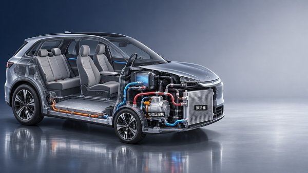
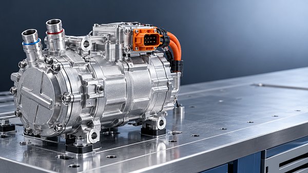
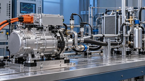
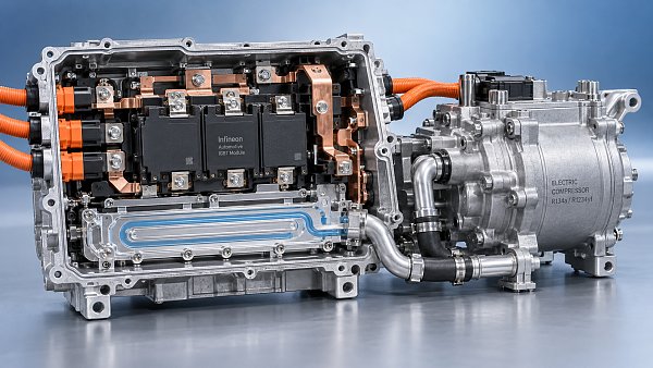
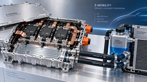
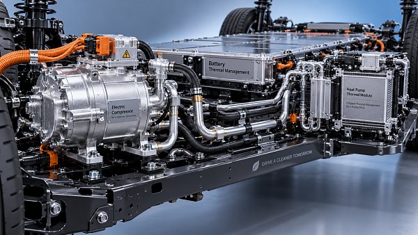
Electric compressor assemblies and thermal-system electrical interfaces deserve particular attention because electrical loading, refrigerant-system heat, vibration, and sealing requirements can coincide. The relevant question is not simply whether the motor, inverter, sensor, or connector meets individual specifications. Review how heat is removed, whether cable and connector routing avoids hot surfaces and chafing, and whether the assembly can maintain insulation and connection integrity through repeated thermal cycling.
For cockpit electronics, heat is sometimes underestimated because the cabin appears benign compared with the engine bay. Displays, processors, power modules, and backlight assemblies may still experience concentrated self-heating, solar loading, restricted airflow, and repeated cabin-temperature cycles. Reliability evidence should cover the actual enclosure, mounting position, and thermal path rather than only the semiconductor or display panel in isolation.
Connector integrity deserves its own review
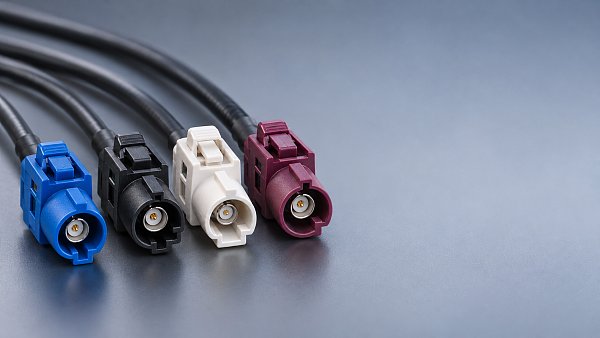
Many field electrical faults are connection faults: fretting corrosion, incomplete terminal insertion, loss of contact force, water ingress, latch damage, pin mismatch, or an apparently secure connector with poor mating compatibility. Because connectors are often sourced as part of a larger assembly, they can receive less scrutiny than the control module or cable they connect. That is a weak point in many evaluations.
Assess the interface as a mated pair, including the production process and vehicle installation. Check whether terminals, housings, seals, plugs, CPA or secondary-lock features, and crimp geometry have been qualified together. Mixed-source combinations may look dimensionally compatible while differing in plating thickness, contact geometry, insertion force, or sealing behavior.
For high-voltage applications, add touch protection, high-voltage interlock continuity, creepage and clearance considerations, shielding termination, and prevention of incorrect mating. A high-voltage connector cannot be evaluated as a scaled-up low-voltage connector; isolation performance and service safety are integral to its reliability case.
Validation data matters only when it represents the application
Qualification reports, environmental test summaries, and certificates can reduce uncertainty, but they should not be treated as interchangeable proof. The most informative evidence connects the component configuration to the intended vehicle use.
Review the tested part number, revision level, materials, supplier manufacturing location, and assembly process. A report for a related family may be useful, yet material substitutions, changes in plating, altered molding compounds, a different cable supplier, or a modified printed circuit board can invalidate assumptions. This is especially important for components with multiple regional variants or alternate sources.
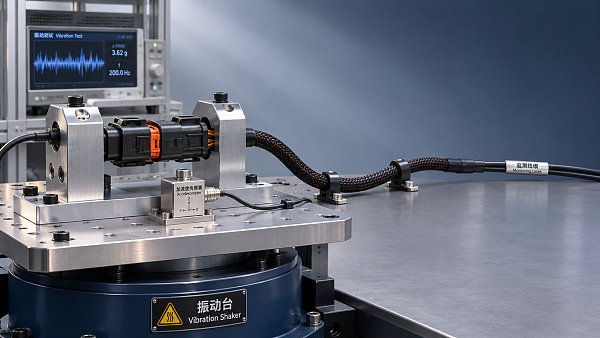
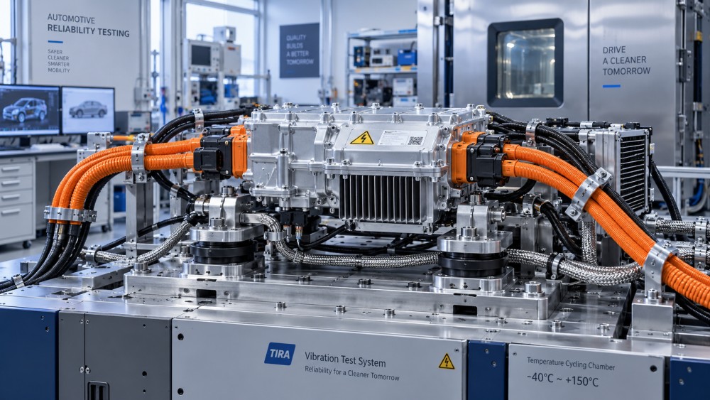
The validation plan should reflect credible stresses: thermal cycling, vibration, mechanical shock, humidity, fluid exposure where relevant, salt exposure for exposed locations, electrical overload or transient behavior, and connector mating cycles. For electronic modules, functional monitoring during or after environmental stress is more meaningful than a purely cosmetic inspection. For harnesses, examine resistance stability, insulation integrity, terminal retention, seal condition, and shielding performance after stress.
Test duration by itself is not enough. A long test at an unrealistic temperature, load, or mounting condition may provide less confidence than a targeted test that reproduces the combined stresses of the vehicle location. Evaluators should also ask what failure criteria were used. “No visible damage” is not an adequate endpoint for a power or data-carrying component if electrical performance, communication quality, or diagnostic behavior is the actual concern.
Evaluate manufacturing control alongside the part design
Reliability is lost when a sound design cannot be reproduced consistently. This risk is particularly high in harnesses and connectorized assemblies, where cutting, stripping, crimping, ultrasonic welding, seal insertion, routing, taping, overmolding, and end-of-line testing all affect final performance.
Technical review should cover traceability of critical materials, process controls for crimps and welds, error-proofing for terminal and seal insertion, continuity and short-circuit testing, high-voltage insulation testing where applicable, and change-management discipline. A supplier should be able to explain how a process change, tooling change, alternate material, or sub-supplier change is assessed before it reaches production.
This does not require treating every supplier disclosure as a formal audit. It does require recognizing that a component’s reliability evidence is incomplete when it covers prototype parts but says little about serial production controls. For a high-consequence assembly, request a clear link between the approved design, manufacturing inspection points, end-of-line tests, and lot traceability.
Use a decision matrix that preserves engineering judgment
A simple weighted matrix can keep commercial pressure from overwhelming critical technical gaps. The weights should differ by component class. High-voltage harnesses may place more weight on insulation, terminal system robustness, shielding, assembly control, and validation under thermal and vibration stress. Cockpit electronics may emphasize power robustness, thermal architecture, software configuration control, EMC evidence, and long-term display or interface behavior.
- Application-fit evidence: operating voltage, current, temperature, location, mechanical loading, and communication requirements.
- Design robustness: material selection, derating, protection functions, sealing, strain relief, thermal path, and interface design.
- Validation relevance: tested configuration, combined-stress coverage, functional pass criteria, and failure analysis quality.
- Manufacturing repeatability: process controls, traceability, end-of-line testing, and change notification.
- Integration risk: mating compatibility, packaging constraints, diagnostics, service access, software or calibration dependencies.
Scores should never conceal a disqualifying issue. A component with excellent cost, delivery, and documentation scores may still be unsuitable if it lacks the necessary high-voltage isolation margin, cannot tolerate the target temperature profile, or relies on an uncontrolled connector interface. Treat these as gate conditions before comparing marginal advantages.
The most dependable shortlist is usually the one supported by a traceable chain of evidence: the operating conditions are defined, the design margins are visible, the mated interfaces are controlled, the tests resemble the intended use, and production can reproduce what was validated. That standard is more useful than a generic ranking when selecting vehicle electrical components expected to remain reliable through years of vibration, heat, power cycling, and service intervention.
Have questions about this sector analysis, or seeking best practices specific to your niche? Drop us a line below and let the senior consultants at GAC assist you.
“We respect your privacy. Your information is strictly confidential.”
Related News
- 00
0000-00
What does each FAKRA cable color code mean? - 00
0000-00
How to compare noise ratings for battery coolant pumps - 00
0000-00
How bright should automotive display systems be in sunlight? - 00
0000-00
How heat pumps improve the efficiency of EV thermal systems - 00
0000-00
Can a smart cockpit platform support multiple displays?
Weekly Insights
Stay ahead with our curated technology reports delivered every Monday.
Recommended News
 What does each FAKRA cable color code mean?FAKRA cable color code explained: Explore common connector colors, typical uses and key compatibility checks before choosing a replacement.Author:Time:Nov 11, 2026
 How to compare noise ratings for battery coolant pumpsCompare coolant pump low noise ratings with confidence. Learn how test conditions, hydraulic duty, tonal noise and installation affect your choice.Author:Time:Nov 10, 2026
 How bright should automotive display systems be in sunlight?Automotive Display Systems need more than brightness to stay readable in sunlight. Discover why 1,000 nits is a starting point and how to evaluate glare and heat.Author:Time:Nov 09, 2026
 How heat pumps improve the efficiency of EV thermal systemsEV Thermal Systems use heat pumps to reduce heating energy demand. Explore how they work, where they excel, and what limits efficiency in cold weather.Author:Time:Nov 08, 2026
 Can a smart cockpit platform support multiple displays?Can a smart cockpit platform support multiple displays? Explore key requirements for performance, safety, connectivity, and supplier evaluation.Author:Time:Nov 07, 2026
 How is automotive connector vibration resistance tested?Automotive connector vibration resistance testing reveals hidden contact failures. Explore test profiles, continuity monitoring and pass criteria.Author:Time:Nov 06, 2026
 How heat pumps save energy in automotive cabin climate systemsAutomotive Cabin Climate Systems energy saving starts with smarter heat pump design. Explore real-world efficiency, cold-weather trade-offs, and testing tips.Author:Time:Nov 05, 2026
 Is an EV heat pump worth it for winter driving range?Is a heat pump worth using in a cold-climate EV? Discover how it affects winter range, when it pays off, and what to check before buying.Author:Time:Nov 04, 2026
 When should you use 50-ohm coaxial cable instead of 75-ohm?Coaxial cable 50 ohm or 75 ohm? Learn when to use each, avoid impedance mismatches, and choose the right cable for reliable RF and video performance.Author:Time:Nov 03, 2026
 How to select a high temperature motor harness for an EVChoose the right high temperature motor harness for your EV. Compare thermal limits, current capacity, shielding, routing, and validation evidence.Author:Time:Nov 02, 2026
 How much does electric power steering replacement cost?Electric power steering price typically ranges from $1,000 to $3,000 for major replacements. Discover cost factors, repair options, and tips for comparing quotes.Author:Time:Nov 01, 2026
 How to size an EV A/C compressor for the required cooling capacitySize an EV A/C Compressor with confidence. Explore cooling loads, performance maps and power limits to select the right compressor for your vehicle.Author:Time:Oct 31, 2026
 How to choose the right pitch for an FPC board connectorFPC board connector pitch affects space, assembly and reliability. Learn how to compare options and select the best fit for your design.Author:Time:Oct 30, 2026
 How zonal design affects harness routing in high-voltage EV architecturesExplore high-voltage electrical architecture zonal design and its impact on EV harness routing. Discover key trade-offs in cable length, safety, thermal performance, and service access.Author:Time:Oct 29, 2026
 How tariffs affect costs in global automotive parts supply chainsNavigate tariffs in the global automotive parts trade supply chain. Learn to compare landed costs, manage duty exposure, and uncover smarter sourcing strategies to protect your margins.Author:Time:Oct 28, 2026
 How to assess vendor lock-in in a software-defined vehicle platformAssess Software-Defined Vehicle platform lock-in with practical tests for API portability, data access, update control, and exit costs. Learn how to choose a platform with a proven exit path.Author:Time:Oct 27, 2026
 How ISO 26262 guides functional safety in steer-by-wire systemsExplore steering systems functional safety through ISO 26262. Learn how hazard analysis, fault-tolerant design, and validation build a stronger steer-by-wire safety case.Author:Time:Oct 26, 2026
 How to evaluate a steering angle sensor manufacturer's accuracy claimsEvaluate steering angle sensor manufacturer accuracy claims with practical checks on calibration, latency, and test evidence. Compare suppliers confidently and avoid costly selection mistakes.Author:Time:Oct 25, 2026
 How to diagnose CAN bus faults in a hybrid vehicle control unitDiagnose Hybrid Vehicle Systems control unit CAN bus faults with step-by-step power, wiring, and waveform checks. Find the root cause and avoid unnecessary replacement.Author:Time:Oct 24, 2026
 How does battery cooling pipe diameter affect coolant pressure drop?Battery Cooling Pipe diameter affects coolant pressure drop and pump power. Explore sizing calculations and practical tips to optimize EV battery cooling and compare options with confidence.Author:Time:Oct 23, 2026
 How to assess PPAP readiness of automotive sensor system manufacturersAssess Automotive Sensor Systems manufacturers for PPAP readiness. Learn to verify production evidence, measurement capability, validation, and traceability to reduce sourcing risks.Author:Time:Oct 22, 2026
 What to ask an FPC connector manufacturer about reliability testingChoosing an FPC Connector manufacturer? Learn what to ask about reliability testing, failure limits, and traceable results to reduce design risks and select with confidence.Author:Time:Oct 21, 2026
 How to verify vehicle fitment for an aftermarket AC evaporatorNavigating the evaporator aftermarket? Verify vehicle fitment with VIN data, OE numbers, and physical interface checks. Use this guide to avoid costly mismatches and order confidently.Author:Time:Oct 20, 2026
 How electric compressor speed affects EV battery cooling capacityElectric compressor technology: battery cooling depends on more than RPM. Discover how speed, refrigerant flow, and system limits affect EV cooling capacity and energy efficiency.Author:Time:Oct 19, 2026
 How to verify a variable frequency compressor supplier’s efficiency claimsVerify a variable frequency compressor supplier’s efficiency claims using COP boundaries, matched test conditions, and duty-cycle data. Learn how to choose with confidence.Author:Time:Oct 18, 2026
 How bend radius affects FPC reliability in automotive camera modulesAutomotive FPC applications: camera module reliability starts with bend radius. Learn how stack-up, strain, and validation guide robust designs and help prevent costly failures.Author:Time:Oct 17, 2026
 How to diagnose intermittent loss of electric power steering assistMaster power steering system diagnostics to trace intermittent EPS assist loss. Learn proven checks for voltage, wiring, and fault codes to avoid costly guesswork.Author:Time:Oct 16, 2026
 How to size automotive power modules for electric compressorsSize automotive power modules for electric compressors with confidence. Learn how voltage, phase current, losses, and cooling shape reliable selection—and avoid costly oversizing.Author:Time:Oct 15, 2026
 Why automotive power electronics are shifting to silicon carbideAutomotive Power Electronics are shifting to silicon carbide. Discover how SiC can cut losses, boost EV power density, and reshape cooling, reliability, and system costs.Author:Time:Oct 14, 2026
 How EV adoption shapes the electrically driven compressor marketExplore how EV adoption shapes the electrically driven compressor market, from battery cooling and heat pumps to supplier margins. Discover the drivers of profitable growth.Author:Time:Oct 13, 2026