How bend radius affects FPC reliability in automotive camera modules




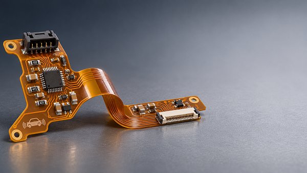
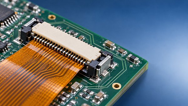
A smaller bend radius increases strain in an FPC’s copper conductors and reduces the margin available for assembly variation, vibration, and thermal movement. In automotive camera modules, a bend that passes initial continuity testing can still develop intermittent connections after repeated mechanical loading. A reliable minimum radius must therefore be tied to the actual flex stack-up, conductor position, installed geometry, and expected movement. A radius-to-thickness ratio alone cannot establish service life.
The first distinction is between a flex formed during assembly and a flex that repeatedly changes curvature. A nominally static camera interconnect can experience local cyclic bending if the sensor board, connector, or housing moves relative to its opposite attachment point. That movement determines whether a compact bend remains an assembly feature or becomes a fatigue location.
Bend radius matters through the strain at the copper
During bending, material outside the neutral axis stretches while material inside it compresses. The neutral axis is the location through the thickness where longitudinal bending strain is approximately zero. For a simple bending estimate, strain at a particular copper layer is approximately its distance from the neutral axis divided by the bend radius measured at that axis:
Approximate bending strain: ε ≈ y / Rn, where y is the distance from the neutral axis to the copper location being assessed and Rn is the neutral-axis radius.
This relationship explains two useful design effects: increasing the radius reduces bending strain, and moving copper closer to the neutral axis reduces strain at a given radius. It also explains why total FPC thickness is an incomplete predictor. Two constructions with the same overall thickness can place their conductors at different distances from the neutral axis.
The estimate assumes a smooth bend with layers acting together. It does not capture local creases, interlayer slip, copper yielding, or stress concentrations around conductor features. In a multilayer flex, the neutral-axis position depends on layer thicknesses and mechanical properties; it should not automatically be placed at the geometric midpoint.
Drawings also need a consistent radius definition. An inside radius, a centerline radius, and a forming-tool radius describe different geometries. Comparing a supplier’s minimum inside radius with a CAD centerline dimension can create an unnoticed shortfall. The specified radius must refer to the finished assembly, including any housing contact that changes the bend shape.
A static installation can contain a dynamic bend
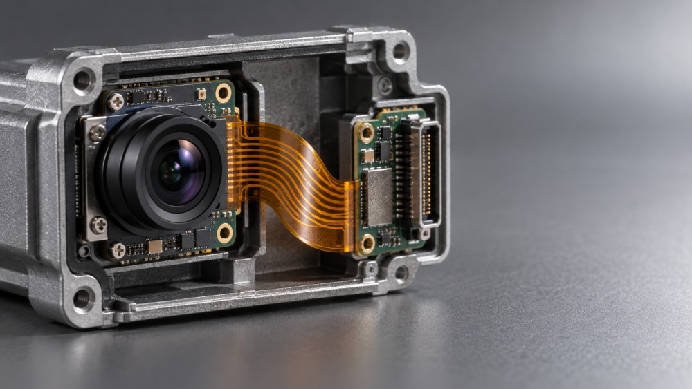
A flex tail folded once between a camera sensor board and an interface board has a different loading history from one that moves repeatedly. During forming, the copper experiences a strain excursion and may retain permanent deformation. If the shape then remains stable, fatigue exposure is limited. Repeated changes in curvature introduce alternating strain, making conductor fatigue a central concern.
Vehicle vibration does not automatically produce significant flex fatigue. The decisive issue is relative movement between attachment points and where that movement is absorbed. When both boards move together within a sufficiently rigid enclosure, the flex may experience little curvature change. If one board moves against the other, a short unsupported section can concentrate the displacement into a small region.
Thermal expansion adds a separate mechanism. Differences in expansion among the housing, circuit boards, and interconnect change the distance or angle between constraints. A bend held tightly against a housing feature can acquire additional tension as the assembly heats or cools. Temperature also changes polymer stiffness, altering how movement is distributed through the flex.
Consequently, a radius suitable for a one-time assembly fold cannot be transferred directly to a repeatedly moving interconnect. The required evidence must address the installed displacement, curvature range, temperature, and cycle exposure. A statement that a flex is “static” needs support from the mechanical assembly.
Stack-up details that change the acceptable radius
Reducing thickness generally helps bending compliance, but the construction determines how much benefit reaches the conductors. A thin single-conductor-layer flex places copper differently from a multilayer construction with planes and adhesive layers. Adding shielding or a ground layer can improve electrical performance while increasing bending stiffness and moving some copper farther from the neutral axis.
Copper type and processing history also matter. Rolled-annealed copper is commonly selected for demanding flex applications because its microstructure supports repeated bending. Electrodeposited copper varies by grade and treatment, so the manufacturing label alone does not establish fatigue performance. Copper thickness, grain characteristics, plating, and the completed fabrication process all belong in the comparison.
Plated features deserve particular attention. A bend region containing locally thickened copper or a plated hole has a different mechanical response from the surrounding flexible trace. Vias, pads, and abrupt conductor-width changes introduce discontinuities that complicate strain distribution. Keeping these features outside the active bend region creates a more predictable flex section.
Adhesive and coverlay construction influence resistance to separation as well as bend stiffness. A conductor can remain electrically intact while the surrounding layers begin to separate. Adhesive squeeze-out, coverlay registration, and local thickness variation can affect the bend transition, especially when packaging leaves little geometric margin.
The smallest local radius controls the problem
A smooth CAD arc can become a sharp fold during installation. Pressing the flex into a narrow channel, closing a cover over trapped material, or pulling a connector into alignment can create a local radius much smaller than the nominal design value. The overall loop may look generous while a short section carries most of the deformation.
Stiffener edges are frequent transition points. A reinforced connector tail resists bending, so movement shifts into the adjacent flexible material. If the intended bend begins at that edge, curvature becomes concentrated. Adequate transition length and a controlled support shape help spread the deformation, but their effectiveness must be assessed in the installed assembly.
Housing contact creates a related issue. A rounded guide can preserve a bend profile; a sharp edge can impose a crease or abrade the coverlay during vibration. Contact pressure matters as well as edge geometry. A flex tightly trapped between parts has less freedom to accommodate dimensional variation and thermal movement.
Assembly sequence therefore belongs in the radius specification. A design that reaches its final position only after reverse bending, twisting, or pulling the tail through a restricted gap exposes the copper to a different strain history from a direct installation. Rework adds further forming cycles. Validation samples should reproduce those operations where they are part of the permitted process.
Trace routing can reduce avoidable stress concentrations. Conductors crossing a defined bend line approximately at right angles follow a simpler bending path than routing that turns within the bend zone. Sharp corners, neck-downs, and pad transitions should remain outside that region where possible. A flex that bends and twists simultaneously requires separate assessment because a single planar radius does not describe its deformation.
Relating mechanical damage to camera performance
Copper fatigue often begins as a partial crack rather than an immediate open circuit. The remaining conductor can carry a low-current continuity measurement while resistance changes with temperature or mechanical position. This explains why a camera module can pass an initial electrical inspection and later show intermittent operation under vibration.
High-speed camera links introduce another sensitivity. Damage to a signal conductor or its return path can disturb transmission before a permanent open circuit appears. Link errors or image interruptions are useful observations, but they do not identify bend damage by themselves. Connector contact problems, shielding discontinuities, and other electrical faults can produce similar symptoms.
Separating these causes requires correlated evidence. Resistance monitoring during controlled movement can reveal position-dependent interruptions. Functional link monitoring shows whether the disturbance affects camera operation. Examination of the bend region then helps establish whether the origin is a conductor crack, layer separation, connector movement, or abrasion.
Bending also changes the physical arrangement of neighboring conductors and nearby metal. Where the folded geometry affects coupling or the return-current path, electrical validation should use the installed shape. A flat test coupon does not reproduce every electrical condition inside a compact camera enclosure.
Validation must represent the finished bend
A supplier’s bend recommendation provides a starting boundary. Its applicability depends on the construction tested, radius definition, forming method, and loading category. A value supported by a single bend test offers different evidence from repeated-flex testing. Neither establishes module reliability without a connection to the installed conditions.
Standards documentation should identify the applicable flexible-board design, fabrication, acceptance, and test requirements, including their revisions. These documents address different aspects of quality. Workmanship acceptance does not establish fatigue life, and passing an environmental test does not validate every bend geometry. Customer-specific requirements and the agreed mission profile determine which evidence is necessary.
A useful validation program connects three levels of evidence:
- Construction-level testing establishes bend behavior using representative copper, dielectric, adhesive, coverlay, and fabrication processes. Generic film samples leave important variables unresolved.
- Assembly trials reproduce forming, connector insertion, enclosure closure, and permitted rework. The resulting local bend profile is compared with the drawing.
- Module testing under relevant environmental loads evaluates the installed constraints while electrical monitoring captures transient interruptions. Where temperature changes stiffness or contact conditions, the test sequence should reflect that interaction.
Acceptance criteria need to distinguish permanent opens, transient interruptions, resistance drift, visible cracking, and delamination. Functional camera operation alone leaves uncertainty about developing damage. Conversely, cosmetic changes need interpretation against the specified acceptance criteria and their relationship to electrical or mechanical deterioration.
Production variation should enter the assessment through credible combinations of flex thickness, stiffener position, board location, connector seating, and housing clearance. A radius demonstrated only on a nominal prototype leaves the tightest permitted assembly unresolved. Physical samples or a tolerance study can identify which combinations produce the smallest radius or greatest constraint.
The released drawing should define the radius reference, bend location, permitted movement, relevant stack-up, and assembly forming method. A change to shielding, adhesive thickness, copper processing, or stiffener position then has a clear basis for reassessment. This makes the minimum bend radius a controlled feature of the camera module rather than an isolated dimension on the flex drawing.
Have questions about this sector analysis, or seeking best practices specific to your niche? Drop us a line below and let the senior consultants at GAC assist you.
“We respect your privacy. Your information is strictly confidential.”
Related News
- 00
0000-00
How does a shielded HSD cable reduce interference in vehicles? - 00
0000-00
What drives demand for scroll compressors in the automotive market? - 00
0000-00
Does AEC-Q200 apply to flexible printed circuits? - 00
0000-00
How does production volume affect automotive flexible electronics costs? - 00
0000-00
How much does an in-vehicle infotainment system cost to replace?
Tags
Weekly Insights
Stay ahead with our curated technology reports delivered every Monday.
Recommended News
 How does a shielded HSD cable reduce interference in vehicles?Discover how a shielded HSD cable reduces vehicle interference, and learn why connector design, routing, and testing matter for reliable high-speed data links.Author:Time:Nov 17, 2026
 What drives demand for scroll compressors in the automotive market?Explore the scroll compressor for automobile market and discover how EV adoption, heat pumps, efficiency, and supplier capabilities shape demand.Author:Time:Nov 16, 2026
 Does AEC-Q200 apply to flexible printed circuits?Flexible Printed Circuit AEC-Q200 requirements explained: discover which components qualify and how to assess automotive FPC reliability.Author:Time:Nov 15, 2026
 How does production volume affect automotive flexible electronics costs?Explore how production volume affects automotive flexible electronics cost, from tooling and yield to testing. Compare quotes and negotiate smarter.Author:Time:Nov 14, 2026
 How much does an in-vehicle infotainment system cost to replace?Explore in-vehicle infotainment cost, from affordable repairs to factory replacements. Compare options, installation fees, and compatibility before you buy.Author:Time:Nov 13, 2026
 How does condenser efficiency affect heat pump performance?Discover how condenser high efficiency can improve heat pump performance, reduce compressor power, and boost heating COP—plus the trade-offs to watch.Author:Time:Nov 12, 2026
 What does each FAKRA cable color code mean?FAKRA cable color code explained: Explore common connector colors, typical uses and key compatibility checks before choosing a replacement.Author:Time:Nov 11, 2026
 How to compare noise ratings for battery coolant pumpsCompare coolant pump low noise ratings with confidence. Learn how test conditions, hydraulic duty, tonal noise and installation affect your choice.Author:Time:Nov 10, 2026
 How bright should automotive display systems be in sunlight?Automotive Display Systems need more than brightness to stay readable in sunlight. Discover why 1,000 nits is a starting point and how to evaluate glare and heat.Author:Time:Nov 09, 2026
 How heat pumps improve the efficiency of EV thermal systemsEV Thermal Systems use heat pumps to reduce heating energy demand. Explore how they work, where they excel, and what limits efficiency in cold weather.Author:Time:Nov 08, 2026
 Can a smart cockpit platform support multiple displays?Can a smart cockpit platform support multiple displays? Explore key requirements for performance, safety, connectivity, and supplier evaluation.Author:Time:Nov 07, 2026
 How is automotive connector vibration resistance tested?Automotive connector vibration resistance testing reveals hidden contact failures. Explore test profiles, continuity monitoring and pass criteria.Author:Time:Nov 06, 2026
 How heat pumps save energy in automotive cabin climate systemsAutomotive Cabin Climate Systems energy saving starts with smarter heat pump design. Explore real-world efficiency, cold-weather trade-offs, and testing tips.Author:Time:Nov 05, 2026
 Is an EV heat pump worth it for winter driving range?Is a heat pump worth using in a cold-climate EV? Discover how it affects winter range, when it pays off, and what to check before buying.Author:Time:Nov 04, 2026
 When should you use 50-ohm coaxial cable instead of 75-ohm?Coaxial cable 50 ohm or 75 ohm? Learn when to use each, avoid impedance mismatches, and choose the right cable for reliable RF and video performance.Author:Time:Nov 03, 2026
 How to select a high temperature motor harness for an EVChoose the right high temperature motor harness for your EV. Compare thermal limits, current capacity, shielding, routing, and validation evidence.Author:Time:Nov 02, 2026
 How much does electric power steering replacement cost?Electric power steering price typically ranges from $1,000 to $3,000 for major replacements. Discover cost factors, repair options, and tips for comparing quotes.Author:Time:Nov 01, 2026
 How to size an EV A/C compressor for the required cooling capacitySize an EV A/C Compressor with confidence. Explore cooling loads, performance maps and power limits to select the right compressor for your vehicle.Author:Time:Oct 31, 2026
 How to choose the right pitch for an FPC board connectorFPC board connector pitch affects space, assembly and reliability. Learn how to compare options and select the best fit for your design.Author:Time:Oct 30, 2026
 How zonal design affects harness routing in high-voltage EV architecturesExplore high-voltage electrical architecture zonal design and its impact on EV harness routing. Discover key trade-offs in cable length, safety, thermal performance, and service access.Author:Time:Oct 29, 2026
 How tariffs affect costs in global automotive parts supply chainsNavigate tariffs in the global automotive parts trade supply chain. Learn to compare landed costs, manage duty exposure, and uncover smarter sourcing strategies to protect your margins.Author:Time:Oct 28, 2026
 How to assess vendor lock-in in a software-defined vehicle platformAssess Software-Defined Vehicle platform lock-in with practical tests for API portability, data access, update control, and exit costs. Learn how to choose a platform with a proven exit path.Author:Time:Oct 27, 2026
 How ISO 26262 guides functional safety in steer-by-wire systemsExplore steering systems functional safety through ISO 26262. Learn how hazard analysis, fault-tolerant design, and validation build a stronger steer-by-wire safety case.Author:Time:Oct 26, 2026
 How to evaluate a steering angle sensor manufacturer's accuracy claimsEvaluate steering angle sensor manufacturer accuracy claims with practical checks on calibration, latency, and test evidence. Compare suppliers confidently and avoid costly selection mistakes.Author:Time:Oct 25, 2026
 How to diagnose CAN bus faults in a hybrid vehicle control unitDiagnose Hybrid Vehicle Systems control unit CAN bus faults with step-by-step power, wiring, and waveform checks. Find the root cause and avoid unnecessary replacement.Author:Time:Oct 24, 2026
 How does battery cooling pipe diameter affect coolant pressure drop?Battery Cooling Pipe diameter affects coolant pressure drop and pump power. Explore sizing calculations and practical tips to optimize EV battery cooling and compare options with confidence.Author:Time:Oct 23, 2026
 How to assess PPAP readiness of automotive sensor system manufacturersAssess Automotive Sensor Systems manufacturers for PPAP readiness. Learn to verify production evidence, measurement capability, validation, and traceability to reduce sourcing risks.Author:Time:Oct 22, 2026
 What to ask an FPC connector manufacturer about reliability testingChoosing an FPC Connector manufacturer? Learn what to ask about reliability testing, failure limits, and traceable results to reduce design risks and select with confidence.Author:Time:Oct 21, 2026
 How to verify vehicle fitment for an aftermarket AC evaporatorNavigating the evaporator aftermarket? Verify vehicle fitment with VIN data, OE numbers, and physical interface checks. Use this guide to avoid costly mismatches and order confidently.Author:Time:Oct 20, 2026
 How electric compressor speed affects EV battery cooling capacityElectric compressor technology: battery cooling depends on more than RPM. Discover how speed, refrigerant flow, and system limits affect EV cooling capacity and energy efficiency.Author:Time:Oct 19, 2026