How is automotive connector vibration resistance tested?




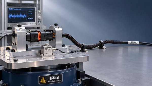
Automotive connector vibration resistance is tested by mounting a mated connector and its attached wiring on a vibration system, exposing the assembly to a specified motion profile, and monitoring electrical continuity while the test is running. Engineers then inspect the connector and compare electrical measurements with the limits in the applicable specification. A connector that remains latched can still fail if its contacts interrupt a circuit or develop excessive resistance.
The mounting arrangement matters because a connector near a powertrain, for example, can experience different vibration inputs and wire movement from one secured behind a cockpit display. An assessment therefore starts with the intended installation and a controlled test specification—not with a generic vibration level.
Start with the specification and installation
Connector vibration requirements may come from an OEM specification, a component standard, or an agreed validation plan. ISO 16750-3 addresses mechanical loads for electrical and electronic equipment in road vehicles; the ISO 8092 series addresses road-vehicle electrical connections; and USCAR specifications may apply where required by the customer. IEC 60068-2-6 and IEC 60068-2-64 provide general procedures for sinusoidal and broadband random vibration testing, respectively.
These documents do not automatically prescribe one interchangeable test for every connector. Confirm the applicable part, edition, test method and severity, as well as any customer-specific amendments. A component-level connector test and an equipment-level test may use different fixtures, monitoring arrangements and acceptance criteria. A report that names a standard without identifying its selected conditions is not enough to reproduce or compare the result.
Before selecting the test profile, define the connector configuration: terminal type and plating, cavity population, seals, backshells, secondary locks, wire gauges and cable routing. The plan should also identify the vehicle mounting location and the expected source of motion. A harness-mounted inline connector may move differently from a connector attached directly to a rigid module; the test fixture should not erase that distinction.
Build a representative test assembly
Prepare specimens using the intended terminals, wire and assembly process. Record crimp tooling and settings where relevant, terminal insertion and retention checks, mating condition, and engagement of primary and secondary locking features. Take baseline contact-resistance measurements and inspect for visible damage before vibration. Otherwise, a pre-existing defect may be mistaken for a vibration-induced failure.
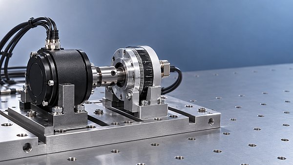
Mount the mated assembly to the shaker fixture in the orientation and at the attachment points defined by the test plan. The fixture should transmit the intended motion without adding uncontrolled looseness or imposing an unrealistic restraint. Wire length, bend radius, breakout geometry, clips and the distance to the first support point can change how much load reaches the terminals. Document them and keep them consistent across comparison samples.
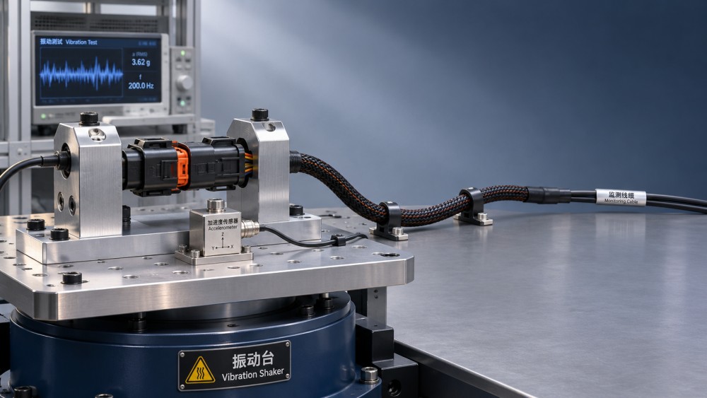
Accelerometers are normally used to control and verify the input at specified locations. Depending on the arrangement, additional measurements may be useful to detect fixture resonances or differences between the control point and the connector mounting point. Confirm that the shaker, fixture and attached wiring can reproduce the requested profile within the permitted tolerance; a nominal shaker setting alone does not establish the motion received by the specimen.
Route monitoring leads so they do not pull on the test wires or bridge a loose contact. Their mass and restraint can alter the response of a small connector. Where temperature conditioning is specified, check that the fixture, sensors, cables and monitoring equipment are suitable for the combined environment.
Apply the vibration profile
The controlled plan should state the excitation type, frequency range, levels, duration, axes and sequence. It should also define any temperature exposure, electrical loading and required inspections between stages. Do not substitute a profile simply because another test uses a similar overall acceleration: frequency content and duration affect the response and damage mechanisms.
A sinusoidal test may be specified in terms of displacement or acceleration, with limits that vary by frequency. Random vibration is commonly defined by a power spectral density curve; the overall root-mean-square acceleration summarizes its energy but does not describe the shape of the spectrum. Two random profiles with the same overall level can excite the connector differently.
Tests often expose each prescribed axis separately. Reorienting the fixture must not change cable support or connector engagement unless the procedure explicitly requires it. If a resonance is detected, follow the specified treatment rather than automatically adding a dwell: an unplanned dwell changes the severity and can make results non-comparable.
Monitor the contacts during motion
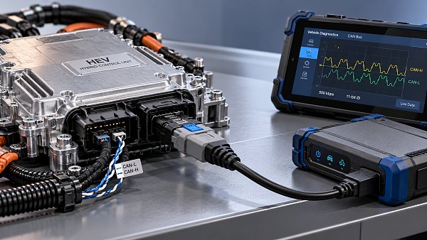
Dynamic continuity monitoring is central to a vibration test because a brief interruption can disappear before a post-test resistance measurement is taken. Connect the monitoring system to the circuits specified in the plan and record the detection threshold, minimum event duration and measurement method. The monitoring bandwidth and sampling capability must be sufficient for the interruptions the specification requires the test to detect.
Not every voltage fluctuation is necessarily a connector failure. Electrical noise, lead movement, an unstable power supply or a fault in the monitoring circuit can produce a suspicious indication. The procedure should define how events are captured and verified without filtering out genuine short-duration discontinuities. Retain the time history or event record where available, together with the vibration axis and test stage.
Electrical loading also needs attention. A low-current continuity circuit may be appropriate for detecting a contact interruption, but it does not automatically demonstrate performance at the connector’s intended operating current. Apply current, voltage and circuit arrangements as required by the governing specification; do not infer high-current suitability from a continuity pass alone. For high-voltage connector assemblies, use equipment and isolation procedures appropriate to the specified test conditions.
A daisy-chain circuit can monitor several contacts, but it may not identify which contact caused an event. Separate channels or a diagnostic arrangement can improve fault localization when the test plan permits them. In either case, document which cavities were populated and monitored: an unmonitored contact cannot be assumed to have passed an electrical continuity criterion.
Inspect and measure after exposure
After the prescribed vibration sequence, inspect the connector before disturbing the assembly where possible. Look for incomplete latch engagement, broken locking features, housing cracks, terminal displacement, wire insulation damage and fretting-related discoloration at accessible contact interfaces. Record the condition before unmating, then inspect the terminals and seals as required by the procedure.
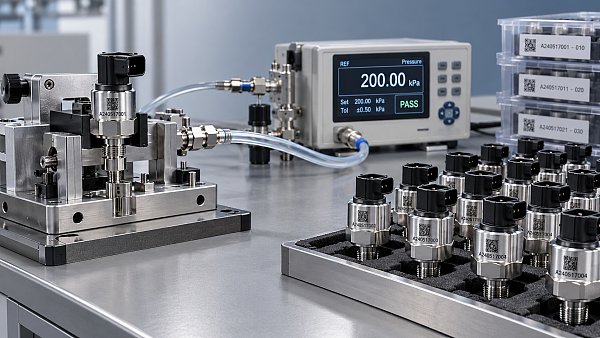
Repeat specified electrical measurements and compare them with both the acceptance limits and the baseline. Contact resistance can be influenced by measurement current, probe placement, lead resistance and temperature, so use the prescribed method consistently. A change from baseline is useful diagnostic evidence, but it is not by itself a failure unless the governing criteria say so.
Mechanical retention, mating or unmating force, insulation resistance and dielectric withstand may also be required before or after vibration. These are separate checks with their own methods and limits; their inclusion depends on the connector design and qualification plan. A test sequence involving temperature, humidity or other conditioning can be significant because prior exposure may change the specimen’s condition before vibration begins.
Interpreting a pass, failure or uncertain result
A valid pass means the tested specimens met the specified electrical and mechanical criteria under the recorded conditions. It does not prove that every installation using the same connector will perform identically. Review the sample size, specimen preparation and test sequence alongside the result, particularly when comparing a supplier report with a different harness layout.
When an interruption occurs, first preserve the evidence and check the monitoring channel. Then trace the affected circuit through the terminal, crimp, wire and test leads. Mechanical inspection can distinguish a latch or terminal-retention issue from wire fatigue or contact motion, although destructive examination may be needed. Do not retest a disturbed specimen as though it were an untouched qualification sample; record any disassembly, repair or change in routing.
For comparisons between connector designs, request the vibration profile and actual control data, fixture description, wire support details, monitored circuits, interruption definition, baseline and final measurements, and photographs or inspection records. If any of these differ, a simple pass-versus-pass comparison may conceal different test severities or detection capabilities. Where the intended installation differs materially from the tested configuration, use the documented gap to decide whether a representative supplementary test is needed.
Have questions about this sector analysis, or seeking best practices specific to your niche? Drop us a line below and let the senior consultants at GAC assist you.
“We respect your privacy. Your information is strictly confidential.”
Related News
- 00
0000-00
How is automotive connector vibration resistance tested? - 00
0000-00
How heat pumps save energy in automotive cabin climate systems - 00
0000-00
Is an EV heat pump worth it for winter driving range? - 00
0000-00
When should you use 50-ohm coaxial cable instead of 75-ohm? - 00
0000-00
How to select a high temperature motor harness for an EV
Weekly Insights
Stay ahead with our curated technology reports delivered every Monday.
Recommended News
 How is automotive connector vibration resistance tested?Automotive connector vibration resistance testing reveals hidden contact failures. Explore test profiles, continuity monitoring and pass criteria.Author:Time:Nov 06, 2026
 How heat pumps save energy in automotive cabin climate systemsAutomotive Cabin Climate Systems energy saving starts with smarter heat pump design. Explore real-world efficiency, cold-weather trade-offs, and testing tips.Author:Time:Nov 05, 2026
 Is an EV heat pump worth it for winter driving range?Is a heat pump worth using in a cold-climate EV? Discover how it affects winter range, when it pays off, and what to check before buying.Author:Time:Nov 04, 2026
 When should you use 50-ohm coaxial cable instead of 75-ohm?Coaxial cable 50 ohm or 75 ohm? Learn when to use each, avoid impedance mismatches, and choose the right cable for reliable RF and video performance.Author:Time:Nov 03, 2026
 How to select a high temperature motor harness for an EVChoose the right high temperature motor harness for your EV. Compare thermal limits, current capacity, shielding, routing, and validation evidence.Author:Time:Nov 02, 2026
 How much does electric power steering replacement cost?Electric power steering price typically ranges from $1,000 to $3,000 for major replacements. Discover cost factors, repair options, and tips for comparing quotes.Author:Time:Nov 01, 2026
 How to size an EV A/C compressor for the required cooling capacitySize an EV A/C Compressor with confidence. Explore cooling loads, performance maps and power limits to select the right compressor for your vehicle.Author:Time:Oct 31, 2026
 How to choose the right pitch for an FPC board connectorFPC board connector pitch affects space, assembly and reliability. Learn how to compare options and select the best fit for your design.Author:Time:Oct 30, 2026
 How zonal design affects harness routing in high-voltage EV architecturesExplore high-voltage electrical architecture zonal design and its impact on EV harness routing. Discover key trade-offs in cable length, safety, thermal performance, and service access.Author:Time:Oct 29, 2026
 How tariffs affect costs in global automotive parts supply chainsNavigate tariffs in the global automotive parts trade supply chain. Learn to compare landed costs, manage duty exposure, and uncover smarter sourcing strategies to protect your margins.Author:Time:Oct 28, 2026
 How to assess vendor lock-in in a software-defined vehicle platformAssess Software-Defined Vehicle platform lock-in with practical tests for API portability, data access, update control, and exit costs. Learn how to choose a platform with a proven exit path.Author:Time:Oct 27, 2026
 How ISO 26262 guides functional safety in steer-by-wire systemsExplore steering systems functional safety through ISO 26262. Learn how hazard analysis, fault-tolerant design, and validation build a stronger steer-by-wire safety case.Author:Time:Oct 26, 2026
 How to evaluate a steering angle sensor manufacturer's accuracy claimsEvaluate steering angle sensor manufacturer accuracy claims with practical checks on calibration, latency, and test evidence. Compare suppliers confidently and avoid costly selection mistakes.Author:Time:Oct 25, 2026
 How to diagnose CAN bus faults in a hybrid vehicle control unitDiagnose Hybrid Vehicle Systems control unit CAN bus faults with step-by-step power, wiring, and waveform checks. Find the root cause and avoid unnecessary replacement.Author:Time:Oct 24, 2026
 How does battery cooling pipe diameter affect coolant pressure drop?Battery Cooling Pipe diameter affects coolant pressure drop and pump power. Explore sizing calculations and practical tips to optimize EV battery cooling and compare options with confidence.Author:Time:Oct 23, 2026
 How to assess PPAP readiness of automotive sensor system manufacturersAssess Automotive Sensor Systems manufacturers for PPAP readiness. Learn to verify production evidence, measurement capability, validation, and traceability to reduce sourcing risks.Author:Time:Oct 22, 2026
 What to ask an FPC connector manufacturer about reliability testingChoosing an FPC Connector manufacturer? Learn what to ask about reliability testing, failure limits, and traceable results to reduce design risks and select with confidence.Author:Time:Oct 21, 2026
 How to verify vehicle fitment for an aftermarket AC evaporatorNavigating the evaporator aftermarket? Verify vehicle fitment with VIN data, OE numbers, and physical interface checks. Use this guide to avoid costly mismatches and order confidently.Author:Time:Oct 20, 2026
 How electric compressor speed affects EV battery cooling capacityElectric compressor technology: battery cooling depends on more than RPM. Discover how speed, refrigerant flow, and system limits affect EV cooling capacity and energy efficiency.Author:Time:Oct 19, 2026
 How to verify a variable frequency compressor supplier’s efficiency claimsVerify a variable frequency compressor supplier’s efficiency claims using COP boundaries, matched test conditions, and duty-cycle data. Learn how to choose with confidence.Author:Time:Oct 18, 2026
 How bend radius affects FPC reliability in automotive camera modulesAutomotive FPC applications: camera module reliability starts with bend radius. Learn how stack-up, strain, and validation guide robust designs and help prevent costly failures.Author:Time:Oct 17, 2026
 How to diagnose intermittent loss of electric power steering assistMaster power steering system diagnostics to trace intermittent EPS assist loss. Learn proven checks for voltage, wiring, and fault codes to avoid costly guesswork.Author:Time:Oct 16, 2026
 How to size automotive power modules for electric compressorsSize automotive power modules for electric compressors with confidence. Learn how voltage, phase current, losses, and cooling shape reliable selection—and avoid costly oversizing.Author:Time:Oct 15, 2026
 Why automotive power electronics are shifting to silicon carbideAutomotive Power Electronics are shifting to silicon carbide. Discover how SiC can cut losses, boost EV power density, and reshape cooling, reliability, and system costs.Author:Time:Oct 14, 2026
 How EV adoption shapes the electrically driven compressor marketExplore how EV adoption shapes the electrically driven compressor market, from battery cooling and heat pumps to supplier margins. Discover the drivers of profitable growth.Author:Time:Oct 13, 2026
 How to size a PTC heater for reliable EV cabin heatingPTC Heater sizing for EV cabins: learn how to balance defrost performance, heat-pump integration, airflow, voltage range, and battery power for reliable winter comfort.Author:Time:Oct 12, 2026
 What determines the cooling output of electric automotive AC compressors?Automotive air conditioning compressors electric systems: explore how speed, voltage, refrigerant, controls, and heat exchangers shape EV cooling capacity and efficiency.Author:Time:Oct 11, 2026
 What makes a touchscreen media head unit responsive enough for daily use?Touchscreen media head unit performance explained: discover what delivers fast starts, smooth maps, reliable phone pairing, and responsive daily driving.Author:Time:Oct 10, 2026
 How Does a Battery Management System Communicate Cooling Demand?How does a battery management system communicate cooling demand? Explore CAN signals, thermal priorities, fault handling, and EV cooling control strategies.Author:Time:Oct 20, 2026
 Can a Domain Controller Share a Cooling Loop with Other Electronics?Can a domain controller share a cooling loop with other electronics? Explore thermal zoning, flow control, safety priorities, and reliable vehicle electronics cooling strategies.Author:Time:Oct 19, 2026