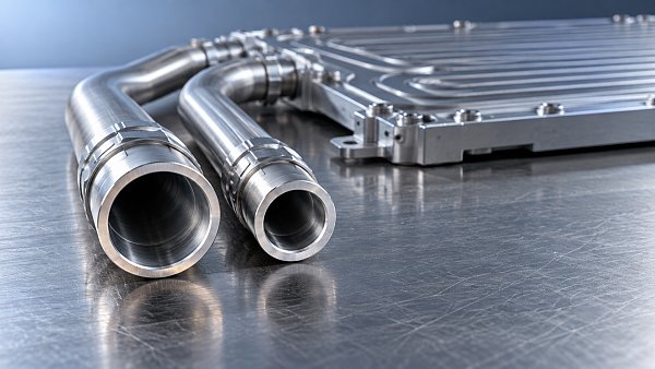
Battery Cooling Pipe diameter determines how much pressure the pump must overcome to deliver the required coolant flow through an electric vehicle battery circuit.
At a fixed volumetric flow rate, smaller internal diameters increase velocity and pressure loss. Larger diameters reduce resistance but require more installation space and coolant.
For technical evaluators, the practical question is whether the selected diameter delivers sufficient battery cooling across operating conditions without excessive pump power or unfavorable flow distribution.
The answer requires checking actual internal diameter, coolant properties, circuit geometry, and the pump operating point. Diameter comparisons become misleading when these conditions differ between suppliers.
How strongly does pipe diameter affect coolant pressure drop?
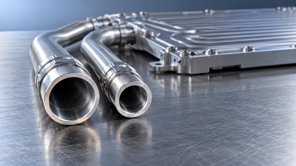
Diameter has a strong, nonlinear influence. For fully developed laminar flow through a straight circular pipe, pressure drop varies inversely with the fourth power of diameter.
For turbulent flow, the relationship is approximately inverse fifth power when friction factor remains constant. In practice, friction factor also changes with Reynolds number and roughness.
This means a modest diameter reduction can produce a substantial pressure penalty. However, these relationships assume the same volumetric flow rate, pipe length, and coolant properties.
For example, increasing internal diameter from 8 to 10 millimeters reduces straight-pipe pressure loss by approximately 67% under the constant-friction-factor approximation at an unchanged flow rate.
Actual reductions depend on the flow regime and component restrictions. A larger connecting pipe delivers limited system improvement when the cold plate dominates total circuit resistance.
Which equations should evaluators use?
The Darcy–Weisbach equation provides the standard starting point for calculating frictional pressure loss in a straight pipe, using the Darcy friction factor rather than the Fanning factor.
- Δp: pressure drop, in pascals.
- f: dimensionless Darcy friction factor.
- L: pipe length, in meters.
- D: internal diameter, in meters.
- ρ: coolant density, in kilograms per cubic meter.
- v: average coolant velocity, in meters per second.
Calculate average velocity from volumetric flow using the actual internal cross-sectional area. For circular pipes, velocity rises with the inverse square of internal diameter at fixed flow.
Next, calculate Reynolds number to identify the likely flow regime. Dynamic viscosity must match the coolant mixture and temperature used in the evaluation case.
For fully developed laminar flow, use f = 64/Re. Combining these equations gives the Hagen–Poiseuille relationship, which makes the fourth-power diameter dependence explicit.
For turbulent flow, select an appropriate friction correlation using Reynolds number and relative roughness. Avoid applying a single correlation indiscriminately across transitional operating conditions.
Conventional Reynolds thresholds are useful screening guides, but entrances, bends, pulsation, and upstream disturbances can influence transition. Validate uncertain cases with representative pressure–flow measurements.
What does a realistic diameter comparison show?
Consider a two-meter straight circular pipe carrying six liters per minute. Assume coolant density of 1,050 kilograms per cubic meter and dynamic viscosity of 0.002 pascal-seconds.
The following estimates use the Blasius smooth-pipe turbulent correlation for Darcy friction factor. They exclude bends, connectors, valves, entrance effects, and battery cold plates.
Increasing diameter from 8 to 10 millimeters cuts calculated straight-pipe loss by about 65%. This illustrates why small dimensional differences deserve attention during technical comparison.
These values are illustrative calculations, not universal product ratings. Different coolant temperatures, surface conditions, or installed geometries can produce materially different pressure losses at identical flow.
The table also cannot establish the best diameter independently. Evaluators must add every relevant circuit restriction and determine how the complete system interacts with the pump.
Why do temperature, fittings, and tolerances change the result?
Cold coolant can become the limiting condition
Water–glycol viscosity changes substantially with temperature and concentration. A diameter that performs adequately with warm coolant may create excessive resistance during a cold start.
In laminar flow, pressure drop increases directly with dynamic viscosity at fixed flow. In turbulent flow, viscosity affects friction factor and may change the flow regime.
Use property data for the specified coolant formulation at the minimum design temperature. Do not substitute room-temperature water data when evaluating a glycol-based battery circuit.
Connectors can erase the benefit of a larger pipe
Bends, tees, quick connectors, and diameter transitions introduce additional losses. These are commonly estimated using loss coefficients, with velocity referenced to the specified local section.
A connector with a narrow internal throat can remain the dominant restriction after the main pipe increases in diameter. Request minimum passage dimensions throughout the assembly.
For complex connectors or valves, measured pressure–flow curves are preferable to generic coefficients. Testing should reproduce relevant valve positions, flow directions, and installed configurations.
Internal diameter matters more than the nominal designation
Nominal size and outer diameter do not establish hydraulic capacity. Wall thickness, manufacturing tolerances, liner geometry, and connector inserts determine the actual available flow area.
As a screening example, a 5% reduction in internal diameter increases predicted loss by roughly 23% under laminar scaling, or 29% under constant-friction turbulent scaling.
Flexible hoses also require installed-condition assessment because tight routing can flatten or kink the passage. Review bend limits and dimensional stability across operating temperatures.
How does diameter affect pump power and battery cooling?
Hydraulic pumping power equals volumetric flow multiplied by pressure rise. Electrical input is higher because pump and motor efficiency are below unity and vary with operating point.
At six liters per minute, the example eight-millimeter pipe consumes approximately 1.7 watts of hydraulic power. At 35% overall efficiency, its equivalent electrical requirement is about 4.9 watts.
This calculation attributes power to one pipe section at the stated efficiency. Actual pump input depends on total circuit pressure loss and the complete pump efficiency map.
A fixed-speed pump generally delivers more flow when resistance falls. Therefore, increasing diameter does not automatically produce the energy savings predicted by a constant-flow comparison.
A controlled pump can potentially reduce speed while maintaining the required flow. Evaluate the resulting operating point against efficiency, available pressure, and control stability requirements.
Cooling performance depends on coolant mass flow, heat capacity, inlet temperature, and cold-plate heat transfer. The coolant temperature rise can be estimated from the energy balance.
Increasing connecting-pipe diameter reduces velocity there, but does not necessarily reduce cold-plate velocity. At unchanged volumetric flow, velocity inside an unchanged cold plate remains unchanged.
Keep connecting-pipe sizing separate from cold-plate channel sizing. Changing channel geometry affects local heat transfer directly and requires additional thermal assessment alongside hydraulic calculations.
What should technical evaluators check before selecting a diameter?
Begin with the required heat rejection and acceptable coolant temperature rise. Use these requirements to establish target flow, then calculate resistance for candidate pipe dimensions.
Build a pressure budget covering pipes, cold plates, valves, manifolds, heat exchangers, and connectors. Allocate losses across the active operating paths and relevant thermal modes.
Assess cold start, fast charging, peak driving load, and other applicable conditions. Different conditions may determine maximum resistance, required cooling flow, or available pump capability.
- Define comparable boundaries: establish whether supplier data cover a bare pipe, a connector assembly, or a complete cooling circuit.
- Confirm hydraulic dimensions: record internal diameter, tolerance, length, minimum connector bore, and installed bend geometry.
- Specify test conditions: require coolant formulation, temperature, flow rate, measurement locations, and instrument uncertainty.
- Compare operating curves: overlay complete circuit resistance with pump performance at relevant speeds and coolant conditions.
- Verify thermal performance: confirm battery temperatures and temperature spread at the resulting branch flows.
For parallel cooling branches, calculate flow distribution rather than assuming equal flow. Differences in diameter, length, connectors, and cold-plate resistance can create unequal coolant delivery.
Increasing header diameter may reduce pressure variation between branch connections. However, branch balancing still requires checking individual resistance and the actual manifold arrangement under representative conditions.
Compare packaging, assembly mass, coolant inventory, cost, and service access alongside pressure loss. A larger diameter is useful only when its system benefit justifies these trade-offs.
Also confirm material compatibility, pressure capability, thermal aging, and joint integrity. Low hydraulic resistance alone does not establish whether a pipe assembly meets vehicle durability requirements.
Choose diameter from the complete circuit requirement
Battery Cooling Pipe diameter strongly affects pressure drop, especially at fixed flow. Small internal diameter reductions can significantly increase resistance, while larger passages can reduce pumping demand.
The appropriate choice balances that hydraulic benefit against packaging and component constraints. Use actual internal dimensions, temperature-dependent coolant properties, and installed geometry to compare candidates consistently.
Select a diameter that delivers required cooling flow across the operating envelope with a justified pressure margin. Confirm the decision using complete circuit calculations and representative testing.