Does AEC-Q200 apply to flexible printed circuits?




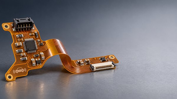
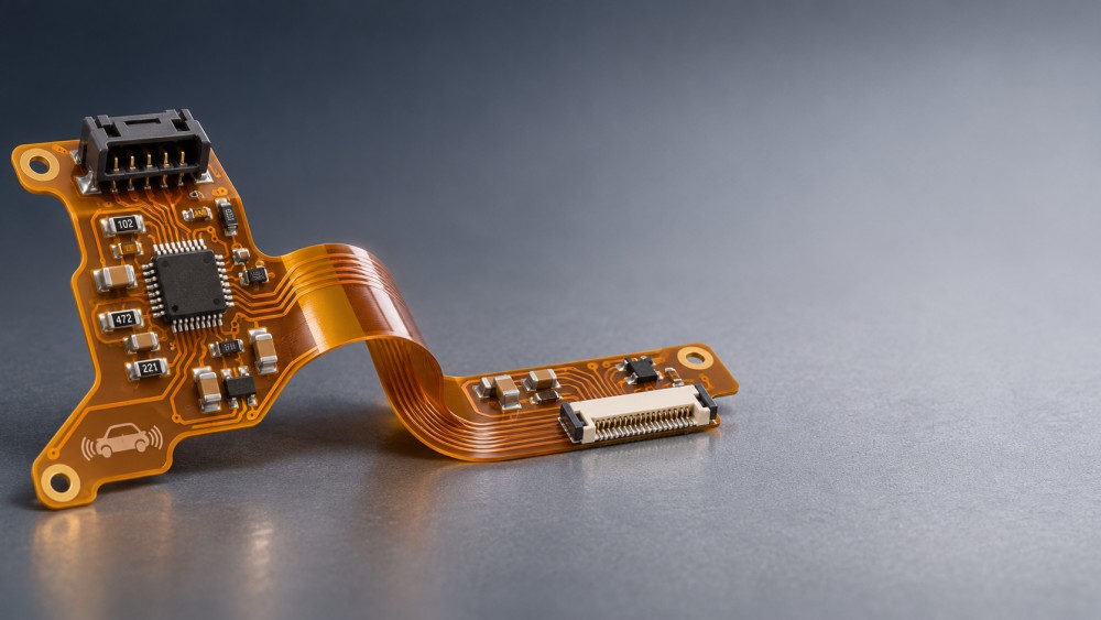
AEC-Q200 does not generally apply to a flexible printed circuit as a complete product category. It is a stress-test qualification standard for passive components. A resistor or capacitor mounted on an automotive flexible printed circuit may fall within its scope, while the bare flexible circuit and the assembled FPC require their own evaluation against applicable board, assembly, customer, and application specifications.
The practical answer to a Flexible Printed Circuit AEC-Q200 question therefore depends on the item being qualified. A qualified passive component can be part of an automotive FPC assembly, but its qualification does not establish that the flex substrate, copper traces, solder joints, connectors, or complete assembly will survive the vehicle environment.
Start by defining the qualification boundary
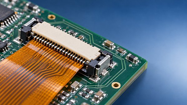
“FPC” can refer to several different deliverables. A supplier may mean a bare flexible circuit, a populated assembly, or a larger module that includes an FPC. Each has different failure mechanisms and calls for different evidence.
The distinction matters when a requirement says only “AEC-Q200 compliant FPC.” That wording does not identify a clear test article. Before accepting a quote or test plan, establish whether the requirement concerns passive components, the bare circuit, the assembled FPC, or a combination of these.
What AEC-Q200 means for components on an FPC
AEC-Q200 addresses stress-test qualification for passive components. Depending on the component type and applicable requirements, the qualification process can include environmental, mechanical, and electrical stresses. The applicable standard revision and component-specific requirements determine which tests and conditions are relevant.
For an automotive FPC populated with resistors or capacitors, request qualification evidence for the actual component part numbers. Review whether the evidence matches the component family, construction, ratings, and intended operating conditions. A statement that a supplier offers “automotive-grade components” is less useful than documentation that identifies the parts being supplied and the qualification basis.
Qualification also has a boundary at the component interface. A passive component may have passed its applicable qualification tests, yet still develop a cracked solder joint when attached to a flex circuit that bends, vibrates, or experiences repeated temperature changes. Component qualification and assembly reliability address related but different risks.
AEC-Q200 should not be used as a generic label for every device on the board. Active devices, connectors, the flexible circuit itself, and other items may be subject to different standards or customer requirements. Identify the relevant requirements by product type and intended use.
Which standards apply to the flexible circuit?
Flexible printed circuits are commonly assessed using applicable IPC specifications for flexible circuit design, materials, qualification, and acceptance, together with the customer’s drawings and procurement requirements. Relevant documents can include IPC-2223 for flexible printed board design, IPC-6013 for qualification and performance, and IPC-A-600 for printed board acceptability. For populated assemblies, IPC-A-610 may be relevant to assembly acceptability.
These documents serve different purposes. A design standard supports choices such as conductor layout and bend construction; a qualification and performance specification addresses requirements for the printed board; an acceptability standard helps define workmanship criteria. Passing a visual inspection alone does not demonstrate that an FPC will withstand repeated bending or the environment inside a vehicle.
Specify the applicable document revision, product class where relevant, and any customer exceptions in the purchase or engineering documentation. Also distinguish a supplier’s ability to manufacture to a specification from evidence that the particular part meets the agreed requirements.
OEM and Tier 1 specifications may add requirements that reflect the installation. These can cover test conditions, sample configuration, inspection methods, acceptance limits, traceability, change control, and the evidence required for approval. An IPC specification and a customer test plan may therefore both be relevant to the same FPC.
Choose reliability tests around the installed design
An FPC’s reliability depends on more than its material designation. Layer construction, copper thickness, bend geometry, stiffeners, surface finish, connector interfaces, assembly processes, and mounting all influence the result. A useful test plan starts with the expected stresses and selects representative test articles and acceptance criteria.
Bending and installation strain
A circuit folded once during installation faces a different demand from one that moves repeatedly in service. For a static bend, assess the final bend radius, routing, strain relief, and whether the circuit is forced against an edge or fastener. For a dynamic application, define the movement, bend location, frequency, and expected service exposure as part of the test plan.
Keep components, solder joints, plated holes, and abrupt changes in stiffness away from highly stressed bend regions where the design permits. A stiffener can support a connector or component area, but the transition between stiff and flexible sections can itself become a strain concentration. Test the finished construction in a representative fixture rather than relying only on a flat coupon.
Temperature and humidity
Temperature exposure and cycling can reveal different problems. Sustained heat may affect materials and adhesives, while changes in temperature can stress interfaces between materials that expand at different rates. A populated FPC adds component terminations and solder joints to those interfaces.
Humidity can affect insulation and, in combination with contamination and electrical bias, contribute to leakage or corrosion. The risk depends on the enclosure, cleanliness, voltage, spacing, and exposure. If the FPC is sealed inside a protected module, the appropriate test conditions may differ from those for a circuit exposed to condensation.
Vibration, handling, and connectors
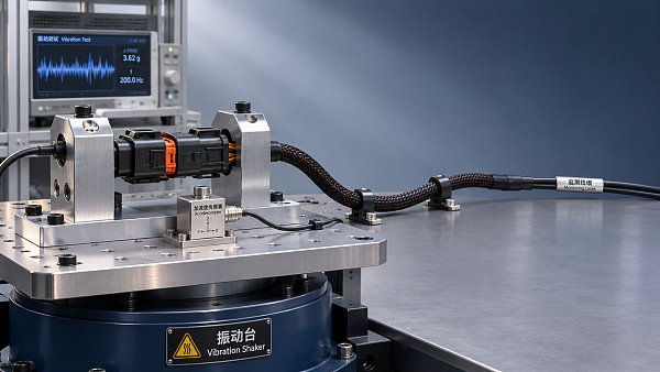
Vibration testing is most informative when the FPC, connectors, supports, and mating hardware reflect the intended installation. An unsupported length can move differently from a secured one; connector retention and local bending may determine the failure mode. Include checks for intermittent electrical faults during the test when the application makes them relevant.
Handling and assembly also deserve attention. A circuit may survive its operating environment but be damaged by repeated connector insertion, sharp folds, rework, or contact with tooling during production. Define handling limits and inspection points where those processes can introduce damage.
Electrical performance before and after stress
Agree on what constitutes a failure before testing begins. Depending on the design, useful checks may include continuity, conductor resistance, insulation resistance, dielectric performance, or functional operation. Visual inspection can help locate damage, but an electrical test is needed to detect faults that are not visible.
For a signal-carrying FPC, continuity alone may not answer every question. Where signal integrity matters, evaluation should reflect the interface and operating conditions of the application. The acceptance limits should come from the circuit’s function and the agreed specification, not from a generic claim that the board is automotive grade.
How to review a supplier’s qualification package
Ask for evidence that connects the supplied design to the requirements. A report is useful only if the test article, construction, conditions, results, and acceptance criteria can be understood in relation to the intended part.
- Identify the deliverable. Establish the part number and revision for the bare FPC, populated assembly, or module being assessed. Obtain the drawing, stack-up, materials, finish, and relevant assembly details.
- Map requirements to each item. List applicable passive-component qualifications separately from bare-board, assembly, and customer requirements. Record the standard revisions and any agreed deviations.
- Review the test configuration. Check whether samples represent the production design, including bends, stiffeners, connectors, components, and mounting where those features affect the result.
- Examine results and limits. Review test conditions, sample size, electrical measurements, observed failures, corrective actions, and the criteria used to judge acceptance.
- Assess differences and changes. A report for a similar FPC may support an assessment, but changes in stack-up, copper pattern, material, assembly process, or installation can change the stress response. Decide whether the existing evidence covers those differences or whether additional testing is needed.
Traceability matters for mounted components as well. A qualification report for a component family should be connected to the actual part being purchased, while the FPC supplier should be able to identify the materials and processes used for the delivered revision. The level of documentation should match the customer’s approval and change-control requirements.
Example: an FPC in an automotive display module
Consider a flexible circuit connecting a display to electronics within a cockpit module. The assembly may include passive components, a connector, and a folded section that fits within the housing. The passive components can be assessed against their applicable AEC-Q200 requirements; the bare flex circuit can be assessed against the specified printed-board requirements; and the finished assembly can be tested in its intended mounting arrangement.
The housing may limit movement during service, making installation folding and connector handling more relevant than repeated flexing. If the same circuit is routed through a moving hinge, the test priorities change: repeated bending and strain at support transitions become central. The component qualification evidence could remain applicable, but it would not answer the new mechanical reliability question.
For a procurement or design review, translate “AEC-Q200 FPC” into a requirement matrix that names each item, its governing specification, the intended operating conditions, and the evidence needed for acceptance. That gives engineering and purchasing teams a basis for deciding whether the supplied parts and the installed assembly are suitable for the same application.
Have questions about this sector analysis, or seeking best practices specific to your niche? Drop us a line below and let the senior consultants at GAC assist you.
“We respect your privacy. Your information is strictly confidential.”
Related News
- 00
0000-00
What does AEC-Q100 qualification mean for automotive camera systems? - 00
0000-00
How to verify a waterproof connector supplier's IP ratings - 00
0000-00
How do air pockets affect automotive coolant systems? - 00
0000-00
How to identify automotive component export opportunities in new markets - 00
0000-00
How to assess a smart cockpit electronics manufacturer's integration capability
Weekly Insights
Stay ahead with our curated technology reports delivered every Monday.
Recommended News
 What does AEC-Q100 qualification mean for automotive camera systems?Automotive Camera Systems AEC-Q100 qualification: Discover what it means for IC reliability, temperature grades and camera validation before approving a design.Author:Time:Nov 22, 2026
 How to verify a waterproof connector supplier's IP ratingsWaterproof connector supplier IP ratings: learn how to verify test reports, match configurations and reduce automotive sourcing risks before you buy.Author:Time:Nov 21, 2026
 How do air pockets affect automotive coolant systems?Automotive Coolant Systems can overheat when air pockets disrupt coolant flow. Discover the warning signs, safe bleeding methods, and when to seek further diagnosis.Author:Time:Nov 20, 2026
 How to identify automotive component export opportunities in new marketsDiscover Automotive Component Export opportunities in new markets by assessing buyer access, technical fit, trade requirements, and landed costs.Author:Time:Nov 19, 2026
 How to assess a smart cockpit electronics manufacturer's integration capabilityAssess a smart cockpit electronics manufacturer's integration capability with practical checks for interfaces, testing, safety, cybersecurity and supplier support.Author:Time:Nov 18, 2026
 How does a shielded HSD cable reduce interference in vehicles?Discover how a shielded HSD cable reduces vehicle interference, and learn why connector design, routing, and testing matter for reliable high-speed data links.Author:Time:Nov 17, 2026
 What drives demand for scroll compressors in the automotive market?Explore the scroll compressor for automobile market and discover how EV adoption, heat pumps, efficiency, and supplier capabilities shape demand.Author:Time:Nov 16, 2026
 Does AEC-Q200 apply to flexible printed circuits?Flexible Printed Circuit AEC-Q200 requirements explained: discover which components qualify and how to assess automotive FPC reliability.Author:Time:Nov 15, 2026
 How does production volume affect automotive flexible electronics costs?Explore how production volume affects automotive flexible electronics cost, from tooling and yield to testing. Compare quotes and negotiate smarter.Author:Time:Nov 14, 2026
 How much does an in-vehicle infotainment system cost to replace?Explore in-vehicle infotainment cost, from affordable repairs to factory replacements. Compare options, installation fees, and compatibility before you buy.Author:Time:Nov 13, 2026
 How does condenser efficiency affect heat pump performance?Discover how condenser high efficiency can improve heat pump performance, reduce compressor power, and boost heating COP—plus the trade-offs to watch.Author:Time:Nov 12, 2026
 What does each FAKRA cable color code mean?FAKRA cable color code explained: Explore common connector colors, typical uses and key compatibility checks before choosing a replacement.Author:Time:Nov 11, 2026
 How to compare noise ratings for battery coolant pumpsCompare coolant pump low noise ratings with confidence. Learn how test conditions, hydraulic duty, tonal noise and installation affect your choice.Author:Time:Nov 10, 2026
 How bright should automotive display systems be in sunlight?Automotive Display Systems need more than brightness to stay readable in sunlight. Discover why 1,000 nits is a starting point and how to evaluate glare and heat.Author:Time:Nov 09, 2026
 How heat pumps improve the efficiency of EV thermal systemsEV Thermal Systems use heat pumps to reduce heating energy demand. Explore how they work, where they excel, and what limits efficiency in cold weather.Author:Time:Nov 08, 2026
 Can a smart cockpit platform support multiple displays?Can a smart cockpit platform support multiple displays? Explore key requirements for performance, safety, connectivity, and supplier evaluation.Author:Time:Nov 07, 2026
 How is automotive connector vibration resistance tested?Automotive connector vibration resistance testing reveals hidden contact failures. Explore test profiles, continuity monitoring and pass criteria.Author:Time:Nov 06, 2026
 How heat pumps save energy in automotive cabin climate systemsAutomotive Cabin Climate Systems energy saving starts with smarter heat pump design. Explore real-world efficiency, cold-weather trade-offs, and testing tips.Author:Time:Nov 05, 2026
 Is an EV heat pump worth it for winter driving range?Is a heat pump worth using in a cold-climate EV? Discover how it affects winter range, when it pays off, and what to check before buying.Author:Time:Nov 04, 2026
 When should you use 50-ohm coaxial cable instead of 75-ohm?Coaxial cable 50 ohm or 75 ohm? Learn when to use each, avoid impedance mismatches, and choose the right cable for reliable RF and video performance.Author:Time:Nov 03, 2026
 How to select a high temperature motor harness for an EVChoose the right high temperature motor harness for your EV. Compare thermal limits, current capacity, shielding, routing, and validation evidence.Author:Time:Nov 02, 2026
 How much does electric power steering replacement cost?Electric power steering price typically ranges from $1,000 to $3,000 for major replacements. Discover cost factors, repair options, and tips for comparing quotes.Author:Time:Nov 01, 2026
 How to size an EV A/C compressor for the required cooling capacitySize an EV A/C Compressor with confidence. Explore cooling loads, performance maps and power limits to select the right compressor for your vehicle.Author:Time:Oct 31, 2026
 How to choose the right pitch for an FPC board connectorFPC board connector pitch affects space, assembly and reliability. Learn how to compare options and select the best fit for your design.Author:Time:Oct 30, 2026
 How zonal design affects harness routing in high-voltage EV architecturesExplore high-voltage electrical architecture zonal design and its impact on EV harness routing. Discover key trade-offs in cable length, safety, thermal performance, and service access.Author:Time:Oct 29, 2026
 How tariffs affect costs in global automotive parts supply chainsNavigate tariffs in the global automotive parts trade supply chain. Learn to compare landed costs, manage duty exposure, and uncover smarter sourcing strategies to protect your margins.Author:Time:Oct 28, 2026
 How to assess vendor lock-in in a software-defined vehicle platformAssess Software-Defined Vehicle platform lock-in with practical tests for API portability, data access, update control, and exit costs. Learn how to choose a platform with a proven exit path.Author:Time:Oct 27, 2026
 How ISO 26262 guides functional safety in steer-by-wire systemsExplore steering systems functional safety through ISO 26262. Learn how hazard analysis, fault-tolerant design, and validation build a stronger steer-by-wire safety case.Author:Time:Oct 26, 2026
 How to evaluate a steering angle sensor manufacturer's accuracy claimsEvaluate steering angle sensor manufacturer accuracy claims with practical checks on calibration, latency, and test evidence. Compare suppliers confidently and avoid costly selection mistakes.Author:Time:Oct 25, 2026
 How to diagnose CAN bus faults in a hybrid vehicle control unitDiagnose Hybrid Vehicle Systems control unit CAN bus faults with step-by-step power, wiring, and waveform checks. Find the root cause and avoid unnecessary replacement.Author:Time:Oct 24, 2026