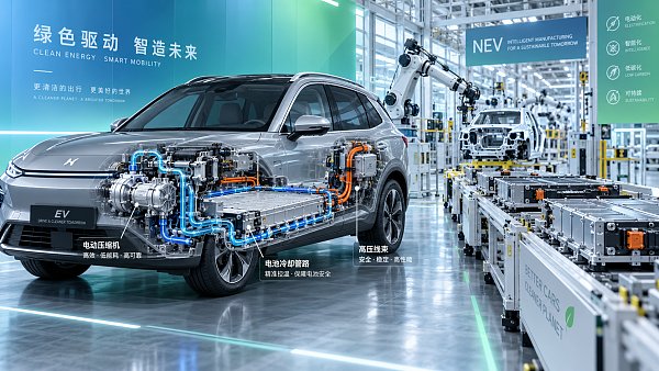
EV Powertrain Components Thermal Integration: Key Trade-Offs in System Layout




Why Layout Decisions Now Start With Thermal Integration
EV packaging used to be discussed mainly in terms of space, mass, and assembly sequence. That is no longer enough.
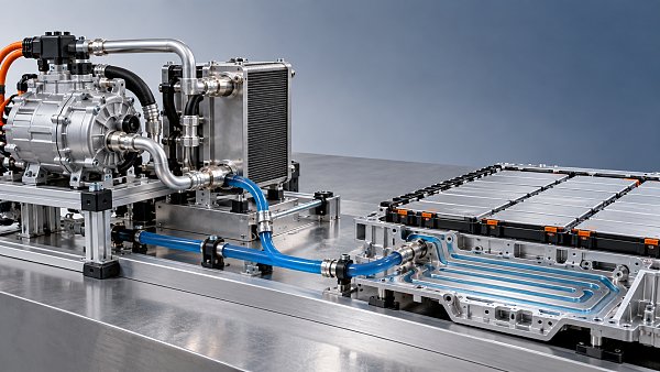
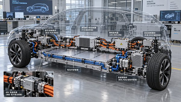
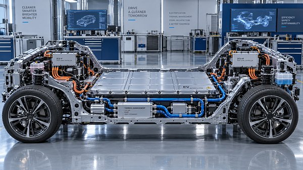
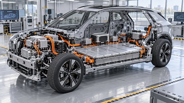
In current platforms, EV Powertrain Components thermal integration shapes efficiency, charging stability, cabin comfort, harness routing, and even service access.
The pressure comes from several directions at once. Battery packs run harder, e-axles become denser, and heat pump systems increasingly share thermal resources.
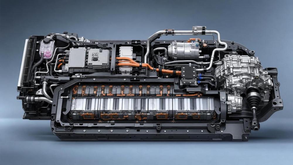
A layout that looks compact on CAD can still create poor coolant distribution, cable congestion, compressor overload, or hard-to-reach valve modules.
That is why EV Powertrain Components thermal integration is no longer a subsystem question. It has become a platform architecture decision.
In practice, the best layout depends on the vehicle mission, regional climate, charging pattern, and how many thermal functions are being coupled.
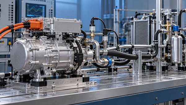
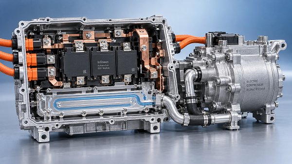
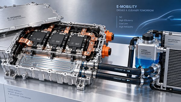
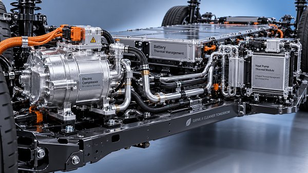
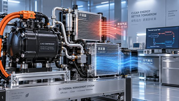
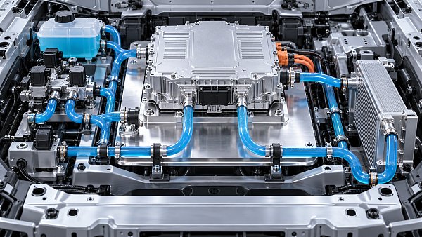
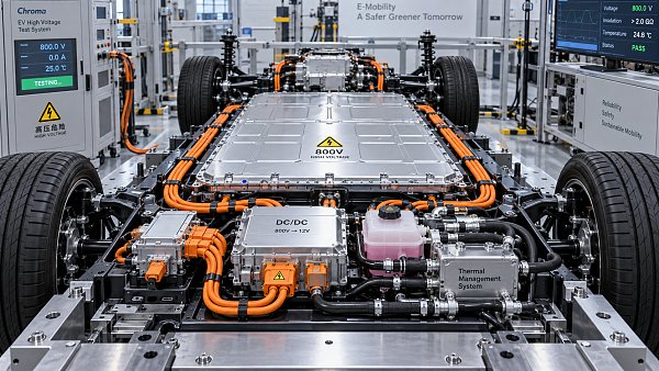
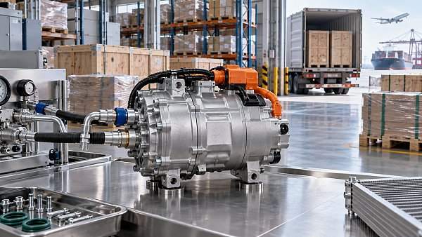
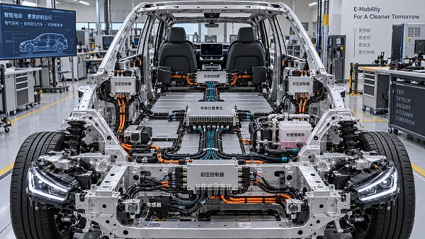
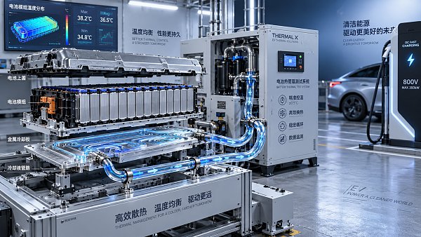
This is also where cross-category insight matters. Battery liquid cooling, electric compressors, integrated thermal valves, and high-voltage harnesses affect one another more than teams often assume.
The Same Platform Logic Does Not Fit Every Vehicle Use Case
Different applications ask different questions from EV Powertrain Components thermal integration. The issue is not only peak temperature control.
Urban passenger EVs often prioritize range consistency, compact front-end packaging, and low NVH from compressors, pumps, and valves.
High-performance models care more about repeated acceleration, aggressive regenerative braking, and thermal recovery after fast charging.
Light commercial EVs usually face another reality. Duty cycles are longer, idle periods differ, and service downtime costs more than a small efficiency gain.
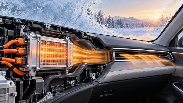
Cold-region vehicles need stronger coordination between battery preconditioning and cabin heating. Hot-climate fleets care more about compressor loading and coolant loop stability.
This is why system layout should be judged by real operating conditions, not by copying a successful architecture from a nearby segment.
A useful way to separate requirements
The table is simple, but it highlights the real issue. Thermal integration succeeds only when the layout reflects vehicle behavior, not generic thermal targets.
When Compact Passenger EVs Push Integration Too Far
In small and mid-size passenger EVs, the strongest pressure usually comes from packaging. Front compartments are crowded and underbody space is already committed.
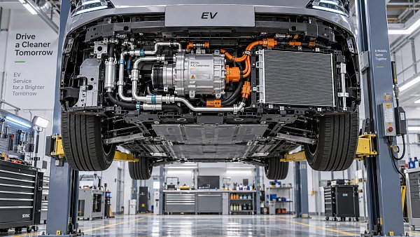
Here, EV Powertrain Components thermal integration often moves toward shared manifolds, integrated valves, and tightly packed refrigerant-coolant interfaces.
The benefit is obvious. Fewer connectors and shorter routing can reduce mass, leak points, and assembly steps.
The trade-off appears later. Dense packaging can restrict hose bend radius, complicate high-voltage harness separation, and raise local thermal coupling around electronics.
A common misjudgment is assuming that shorter flow paths always mean better results. In reality, uneven flow balance and poor purge behavior can offset that gain.
A more reliable approach is to evaluate loop interaction early. Check whether battery cooling, cabin heating, and e-drive cooling compete during the same urban cycle.
If those loads overlap often, a slightly less compact layout may deliver better seasonal efficiency and simpler fault isolation.
Performance Platforms Need Margin, Not Just Integration Density
On performance-oriented EVs, thermal integration is judged less by module count and more by recovery speed under repeated load events.
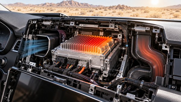
Fast charging, hard acceleration, and sustained high inverter output create overlapping peaks. Shared loops may save space, but they can also spread thermal stress.
This is where EV Powertrain Components thermal integration needs controlled decoupling. Some circuits should share resources, while critical nodes need protection from transient spikes.
For example, integrating e-motor, inverter, and gearbox cooling may look efficient. Yet if control logic cannot prioritize the hottest component fast enough, performance derating arrives early.
The practical decision point is not whether to integrate, but where to preserve thermal margin.
- Keep high-response sensors close to known hot spots, not only at loop inlets and outlets.
- Validate compressor and pump control under back-to-back charging and acceleration events.
- Reserve service access around valves and connectors likely to see repeated thermal cycling.
In these vehicles, the cost of inadequate margin is usually higher than the cost of one extra routing branch or control device.
Commercial Duty Cycles Change the Best Answer
In vans, delivery EVs, and other work-focused platforms, EV Powertrain Components thermal integration is often judged by uptime and predictable maintenance windows.
These vehicles may not chase the most advanced integrated architecture. They need stable cooling under variable payloads, mixed speeds, and long operating hours.
Over-integration becomes a problem when replacing one failed unit requires draining multiple loops or removing adjacent electrical hardware.
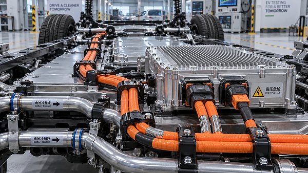
This is especially relevant where electric compressors, battery chillers, and valve blocks are packed near wiring harness corridors.
The better commercial layout usually separates maintenance-sensitive components without fully abandoning thermal sharing.
In actual fleet use, a serviceable architecture often outperforms a highly integrated one over the full lifecycle, even if the nominal efficiency is slightly lower.
What to confirm before freezing the layout
- Drain and refill sequence for every loop after common repairs.
- Access clearance for high-voltage harnesses near thermal modules.
- Field replacement impact if a valve, pump, or compressor fails.
- Contamination risk when coolant and refrigerant systems sit too close.
Where Teams Commonly Misread Thermal Integration Trade-Offs
Several mistakes appear repeatedly across programs, even when simulation data looks convincing.
One is treating similar body styles as thermally equivalent. Wheelbase, frontal area, cabin volume, and charging profile can shift the correct layout choice.
Another is focusing on component efficiency alone. EV Powertrain Components thermal integration must also be checked against controls maturity and supplier coordination.
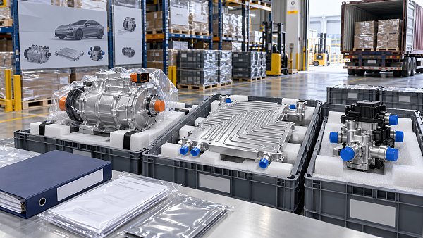
There is also a supply-chain angle. Highly integrated modules may simplify assembly, yet create sourcing concentration or regional validation delays.
That matters in global programs spanning China, Europe, the United States, India, and Southeast Asia, where standards, climate conditions, and service ecosystems differ.
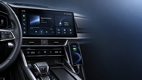
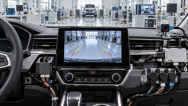
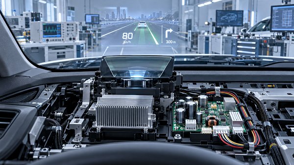
Another overlooked point is the interaction between thermal layout and adjacent systems, including cockpit electronics, displays, and high-voltage data cables.
As vehicle electronics density rises, thermal decisions increasingly affect electromagnetic compatibility, connector life, and routing discipline.
A Practical Way to Judge the Right Level of Integration
The most useful question is not whether EV Powertrain Components thermal integration is good or bad. The real question is how much integration the use case can absorb.
A workable evaluation path usually combines thermal load mapping, packaging review, service simulation, and regional operating assumptions.
In practice, four checks help narrow the answer.
- Map concurrent heat loads during charging, climbing, towing, or heavy HVAC demand.
- Review whether integrated valves and shared loops simplify or complicate fault isolation.
- Compare assembly savings against refill time, repair access, and replacement parts strategy.
- Test the layout under climate extremes rather than average-cycle assumptions.
This kind of cross-check aligns well with how GACT tracks thermal systems, compressors, wiring architectures, and adjacent component trends across global automotive markets.
The value is not in abstract theory. It is in seeing how component categories connect when an EV platform moves from concept to production reality.
A sensible next step is to define the dominant operating scenarios first, then compare layout options against thermal margin, routing complexity, service effort, and regional compliance needs.
That approach usually produces better decisions than optimizing around a single peak number. It also makes EV Powertrain Components thermal integration easier to validate, source, and maintain over time.
Related News
- 00
0000-00
How electric compressor speed affects EV battery cooling capacity - 00
0000-00
How to verify a variable frequency compressor supplier’s efficiency claims - 00
0000-00
How bend radius affects FPC reliability in automotive camera modules - 00
0000-00
How to diagnose intermittent loss of electric power steering assist - 00
0000-00
How to size automotive power modules for electric compressors
Weekly Insights
Stay ahead with our curated technology reports delivered every Monday.
Recommended News
 How electric compressor speed affects EV battery cooling capacityElectric compressor technology: battery cooling depends on more than RPM. Discover how speed, refrigerant flow, and system limits affect EV cooling capacity and energy efficiency.Author:Time:Oct 19, 2026
 How to verify a variable frequency compressor supplier’s efficiency claimsVerify a variable frequency compressor supplier’s efficiency claims using COP boundaries, matched test conditions, and duty-cycle data. Learn how to choose with confidence.Author:Time:Oct 18, 2026
 How bend radius affects FPC reliability in automotive camera modulesAutomotive FPC applications: camera module reliability starts with bend radius. Learn how stack-up, strain, and validation guide robust designs and help prevent costly failures.Author:Time:Oct 17, 2026
 How to diagnose intermittent loss of electric power steering assistMaster power steering system diagnostics to trace intermittent EPS assist loss. Learn proven checks for voltage, wiring, and fault codes to avoid costly guesswork.Author:Time:Oct 16, 2026
 How to size automotive power modules for electric compressorsSize automotive power modules for electric compressors with confidence. Learn how voltage, phase current, losses, and cooling shape reliable selection—and avoid costly oversizing.Author:Time:Oct 15, 2026
 Why automotive power electronics are shifting to silicon carbideAutomotive Power Electronics are shifting to silicon carbide. Discover how SiC can cut losses, boost EV power density, and reshape cooling, reliability, and system costs.Author:Time:Oct 14, 2026
 How EV adoption shapes the electrically driven compressor marketExplore how EV adoption shapes the electrically driven compressor market, from battery cooling and heat pumps to supplier margins. Discover the drivers of profitable growth.Author:Time:Oct 13, 2026
 How to size a PTC heater for reliable EV cabin heatingPTC Heater sizing for EV cabins: learn how to balance defrost performance, heat-pump integration, airflow, voltage range, and battery power for reliable winter comfort.Author:Time:Oct 12, 2026
 What determines the cooling output of electric automotive AC compressors?Automotive air conditioning compressors electric systems: explore how speed, voltage, refrigerant, controls, and heat exchangers shape EV cooling capacity and efficiency.Author:Time:Oct 11, 2026
 What makes a touchscreen media head unit responsive enough for daily use?Touchscreen media head unit performance explained: discover what delivers fast starts, smooth maps, reliable phone pairing, and responsive daily driving.Author:Time:Oct 10, 2026
 Can a Domain Controller Share a Cooling Loop with Other Electronics?Can a domain controller share a cooling loop with other electronics? Explore thermal zoning, flow control, safety priorities, and reliable vehicle electronics cooling strategies.Author:Time:Oct 19, 2026
 What Causes Domain Controller Overheating During Summer Testing?What causes domain controller overheating in summer testing? Explore heat load, airflow, installation, software factors, and practical fixes.Author:Time:Oct 18, 2026
 Is a Head-Up Display Hard to Integrate with Different Windshields?Is a head-up display difficult to integrate with different windshields? Discover how glass geometry, coatings, and calibration affect HUD clarity, cost, and production readiness.Author:Time:Oct 17, 2026
 What Should Be Checked Before Selecting an Automotive Head Unit?What should be checked before selecting an automotive head unit? Explore compatibility, performance, cybersecurity, compliance, and supplier support.Author:Time:Oct 16, 2026
 Is Steer-by-Wire More Expensive Than an EPS Steering System?Is steer-by-wire more expensive than an EPS steering system? Explore the true costs, safety demands, software value, and when SbW justifies its premium.Author:Time:Oct 15, 2026
 Which Automotive Electronics Need Validation for 800V Platforms?What automotive electronics should be validated for 800V platforms? Explore critical checks for harnesses, power electronics, thermal systems, safety, and EMC.Author:Time:Oct 14, 2026
 How Do Automotive Compressor Export Requirements Vary by Market?How do automotive compressor export requirements vary by market? Explore key compliance rules for refrigerants, EV safety, OEM approvals, labeling, and customs.Author:Time:Oct 13, 2026
 What Documents Are Needed to Export Automotive Thermal Components?What documents are needed to export automotive thermal components? Explore customs, compliance, technical records, and shipping tips to prevent costly delays.Author:Time:Oct 12, 2026
 How Often Should an EV Air Conditioning Compressor Be Inspected?How often should an EV air conditioning compressor be inspected? Discover recommended service intervals, warning signs, and expert care tips to protect cooling performance and EV reliability.Author:Time:Oct 11, 2026
 How to size power solutions for automotive head-up display systemsHeads-up display systems power solutions: learn how to size automotive HUD power architectures for startup, brightness, thermal limits, EMC, protection, and reliable vehicle operation.Author:Time:Oct 19, 2026
 How does a head-up display work in a high-performance car?Hoe werkt een head-up display in een high-performance auto en welke informatie toont het? Discover the tech, safety alerts, and performance data that sharpen every drive.Author:Time:Oct 18, 2026
 Which trends will shape zonal EV architectures in the next decade?Future trends in zonal EV architectures: explore smarter power distribution, 48V systems, thermal integration, software, and resilient networks shaping next-gen vehicles.Author:Time:Oct 17, 2026
 When does a zonal EV architecture outperform a centralized design?Explore the trade-offs between zonal and centralized EV architectures to identify the best path for harness efficiency, software scalability, safety, and faster EV launches.Author:Time:Oct 16, 2026
 How to compare vendors for zonal EV power architecturesComparing vendors for zonal EV power architectures: assess electrical capability, interface ownership, lifecycle support, and integration risk for smarter sourcing.Author:Time:Oct 15, 2026
 How zonal architectures can improve EV reliability at the system levelHow zonal architectures affect EV reliability: explore fault containment, diagnostics, power resilience, and software strategies for more dependable electric vehicles.Author:Time:Oct 14, 2026
 What is driving growth in the automotive E/E architecture market?Explore what drives the automotive electric electronic systems architecture market, from EV power systems and zonal computing to ADAS, cybersecurity, and software-defined vehicles.Author:Time:Oct 13, 2026
 How to evaluate top-rated vehicle electrical components for reliabilityDiscover how to evaluate top-rated vehicle electrical components for reliability, from connector integrity and thermal margins to validation data and manufacturing control.Author:Time:Oct 12, 2026
 What makes vehicle electrical components reliable over a long service life?Top-rated vehicle electrical components for reliability depend on thermal control, sealing, vibration resistance, and validated manufacturing. Discover how to choose durable parts.Author:Time:Oct 11, 2026
 How battery thermal management solutions prevent fast-charge overheatingBattery thermal management solutions prevent fast-charge overheating with intelligent cooling, valve control, predictive preconditioning, and reliable heat rejection.Author:Time:Oct 09, 2026
 What an automotive market report can reveal about EV demand shiftsAutomotive market report insights reveal EV demand shifts, component opportunities, regional risks, and smarter investment strategies for growth.Author:Time:Oct 08, 2026