Automotive ECU Controller Basics: Functions, Signals, and Integration Points




Why does an Automotive ECU controller matter so much today?
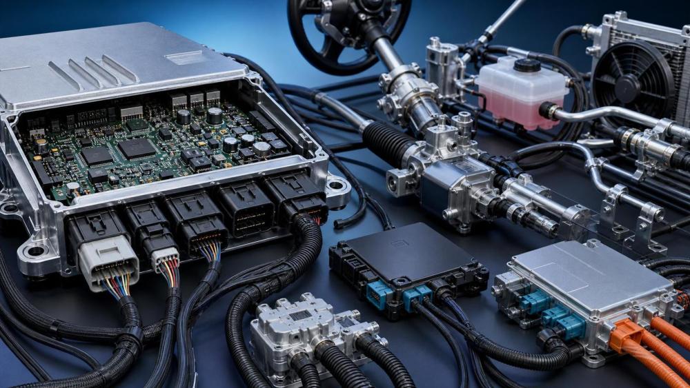
An Automotive ECU controller is no longer a hidden box with a narrow task.
It has become the logic center behind sensing, calculation, communication, and actuation across the vehicle.
That matters because modern cars depend on coordinated electronics more than isolated mechanical control.
In practical terms, the controller reads sensor inputs, applies rules or software models, and sends output commands.
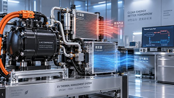
Those commands can affect cooling valves, compressors, steering support, displays, battery systems, and network messaging.
This is why the Automotive ECU controller sits at the center of electrification and intelligent vehicle architecture.
A useful way to think about it is simple.
Sensors tell the vehicle what is happening.
Actuators make something happen.
The Automotive ECU controller decides what should happen next, and how fast.
Across industry tracking platforms such as GACT, this controller is a recurring reference point.
That is because thermal systems, smart cockpit electronics, steering systems, and wiring harnesses all depend on control logic.
When people compare product categories or technology routes, they often end up comparing controller capability.
What exactly does an Automotive ECU controller do inside a vehicle?
The short answer is that it converts raw signals into usable vehicle decisions.
The fuller answer is more interesting, because its functions vary by subsystem and vehicle platform.
A controller in thermal management behaves differently from one in steering or cockpit electronics.
Still, most Automotive ECU controller designs share several core functions:
- Signal acquisition from sensors such as temperature, pressure, speed, position, voltage, and current.
- Data filtering to remove noise and convert analog values into reliable digital information.
- Control logic execution based on calibration maps, software rules, and safety thresholds.
- Command output to motors, valves, relays, pumps, compressors, displays, or steering assist units.
- Network communication over CAN, LIN, Ethernet, or other in-vehicle communication buses.
- Diagnostics, fault logging, and fallback control when a signal becomes invalid.
In actual applications, this means the same control principle appears in many different products.
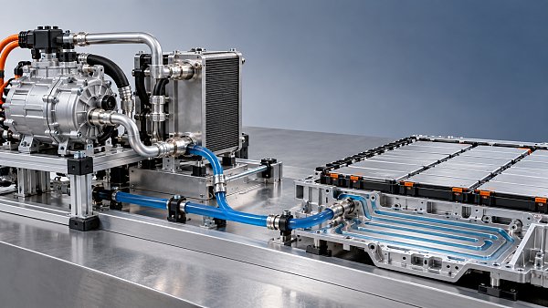
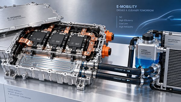
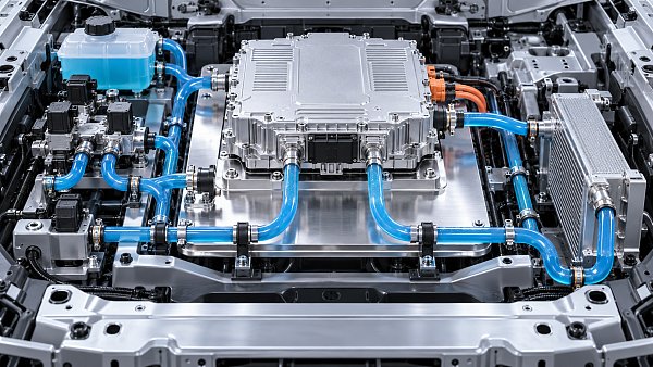
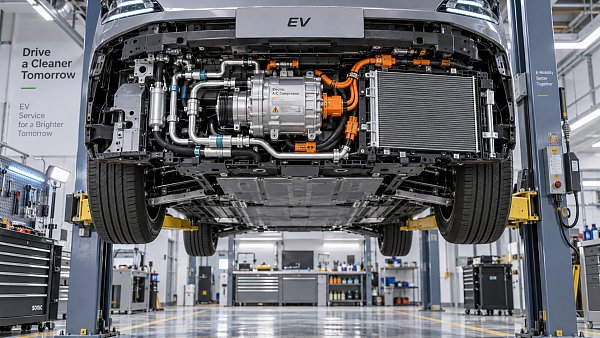
For example, battery liquid cooling systems need temperature and flow control.
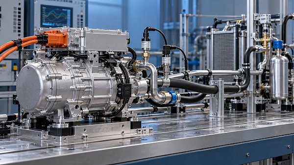
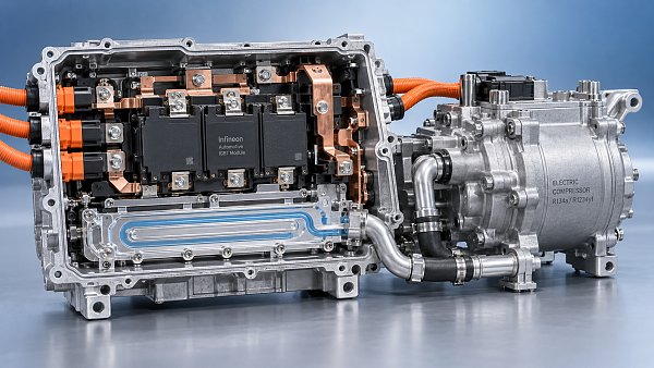
Electric compressors need speed control and protection logic.
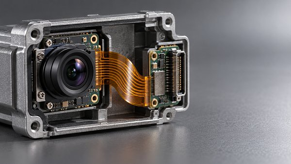
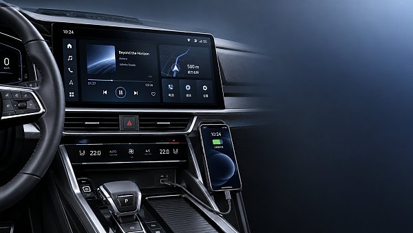
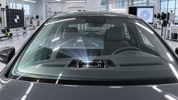
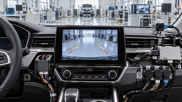
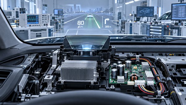
HUD systems and cockpit displays need stable communication and coordinated power management.
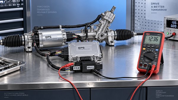
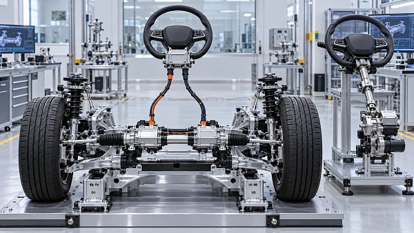
EPS and steer-by-wire systems need fast response, redundancy awareness, and strict diagnostic behavior.
So when evaluating an Automotive ECU controller, function means more than simple control.
It also includes timing, fault strategy, communication quality, and software maturity.
Which signals are most important, and how should they be interpreted?
A common question is whether signals are just inputs and outputs.
They are, but the more useful view is to group them by purpose.
That makes Automotive ECU controller analysis much easier.
The table helps because not every signal has equal diagnostic value.
For instance, a noisy temperature signal can distort thermal control.
A delayed CAN message can break coordination between cooling, powertrain, and cabin electronics.
A weak ground path can create confusing symptoms that look like software issues.
More often, signal interpretation comes down to three checks:
- Is the signal physically valid?
- Is the timing acceptable for the control task?
- Does the receiving controller interpret it the same way?
That third point is often underestimated during integration.
A signal can be present, yet still unusable because scaling, units, message timing, or fault coding do not match.
Where are the main integration points engineers usually watch first?
An Automotive ECU controller rarely works alone.
Its real value appears when it is integrated into the wider electrical and electronic architecture.
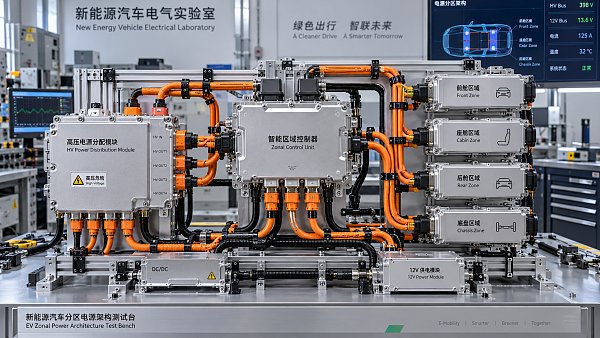
The most important integration points usually sit in four areas.
Power supply and grounding
Stable power is basic, but it shapes controller behavior more than many expect.
Voltage drops, load dump events, and poor grounding can trigger resets or false diagnostics.
Wiring harness and connector design
Signal integrity depends heavily on harness routing, shielding, connector quality, and pin definition.
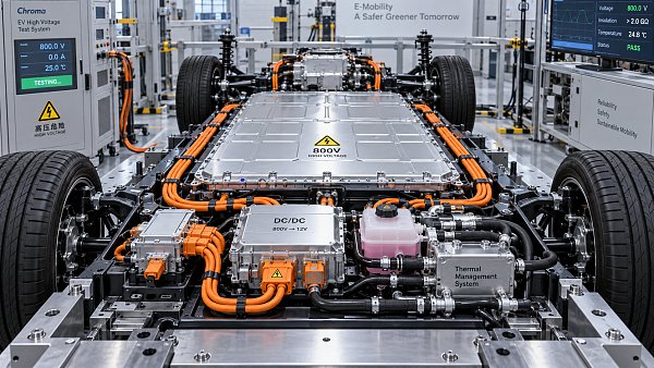
This is especially relevant for high-voltage harnesses and data communication cables.
Network architecture
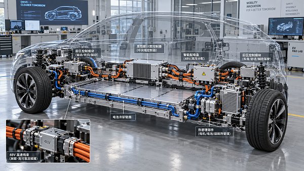
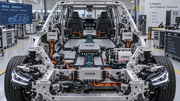
The controller must exchange messages with gateways, domain controllers, battery systems, cockpit modules, and chassis units.
Poor message design can create latency, bus overload, or incompatible software updates.
Subsystem logic coordination
Thermal, steering, compressor, and cabin functions increasingly interact with one another.
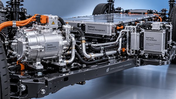
A battery cooling request may affect compressor load, cabin comfort, and energy management at the same time.
This is why cross-category intelligence matters.
On GACT, components such as heat pump systems, electric compressors, cockpit electronics, EPS systems, and harness technologies are often analyzed together.
The reason is straightforward.
Integration problems usually appear between systems, not inside one part alone.
How do you judge whether one Automotive ECU controller setup is better than another?
A better setup is not always the one with the most features.
The better setup is the one that fits the control task, system complexity, and validation target.
In real selection or benchmarking work, these are the practical checkpoints:
- Processing performance for the expected signal load and response time.
- Communication compatibility with current and future vehicle networks.
- Diagnostic depth, including fault memory, freeze-frame data, and fail-safe behavior.
- Software update path and calibration flexibility during development and service.
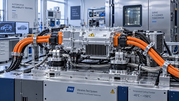
- Environmental durability for vibration, temperature, humidity, and EMC exposure.
- Functional safety expectations, especially in steering and high-voltage related functions.
There is also a timing issue that often gets missed.
A capable Automotive ECU controller may still underperform if software calibration lags behind hardware integration.
That is common in fast-moving NEV programs where thermal efficiency, range targets, and cockpit features evolve together.
So the comparison should not stop at chip resources or I/O count.
It should include validation readiness, calibration effort, and supply chain consistency.
What mistakes create the biggest risk during integration and diagnostics?
Most failures are not caused by one dramatic flaw.
They come from small mismatches between electrical design, software assumptions, and vehicle-level operating conditions.
The most common mistakes are usually these:
- Assuming a valid sensor signal is automatically a usable control signal.
- Ignoring grounding, shielding, and connector detail in early architecture reviews.
- Treating communication timing as a software issue only, not a system issue.
- Underestimating thermal interactions between battery, cabin, and compressor control.
- Using generic diagnostic logic in functions that need application-specific fault handling.
- Delaying cross-system validation until late prototype stages.
A practical warning is worth adding here.
When a vehicle adopts more centralized electronics, the Automotive ECU controller may gain stronger coordination duties.
That can simplify architecture, yet it also increases dependency on clean interfaces.
As a result, diagnostics must be designed around interactions, not only component faults.
This is especially relevant in markets where export compliance, standards interpretation, and platform reuse are under close review.
So what is the best next step when studying an Automotive ECU controller?
Start with the control objective, not the controller label.
Ask which physical function must be controlled, which signals are trusted, and which systems must cooperate.
Then map the Automotive ECU controller against three layers.
- Component layer: sensors, actuators, power, and connector layout.
- Communication layer: bus type, message timing, gateway logic, and diagnostics.
- Application layer: thermal strategy, chassis response, cockpit behavior, and energy coordination.
That approach gives a cleaner basis for comparison than relying on part names alone.
It also helps when tracking technology shifts across regions and product segments.
An Automotive ECU controller is ultimately a system decision point.
Its quality shows up in response consistency, integration stability, and diagnostic clarity.
For deeper evaluation, it makes sense to compare signal paths, interface definitions, thermal interactions, and validation scope side by side.
That is usually where the most meaningful differences appear.
Related News
- 00
0000-00
How electric compressor speed affects EV battery cooling capacity - 00
0000-00
How to verify a variable frequency compressor supplier’s efficiency claims - 00
0000-00
How bend radius affects FPC reliability in automotive camera modules - 00
0000-00
How to diagnose intermittent loss of electric power steering assist - 00
0000-00
How to size automotive power modules for electric compressors
Tags
- thermal systems
- electric compressors
- steer-by-wire
- heat pump systems
- domain controllers
- smart cockpit electronics
- smart cockpit
- cockpit displays
- data communication cables
- battery liquid cooling
- automotive Ethernet
- steering systems
- Automotive ECU
- Cabin Electronics
- Automotive ECU controller
- liquid cooling systems
Weekly Insights
Stay ahead with our curated technology reports delivered every Monday.
Recommended News
 How electric compressor speed affects EV battery cooling capacityElectric compressor technology: battery cooling depends on more than RPM. Discover how speed, refrigerant flow, and system limits affect EV cooling capacity and energy efficiency.Author:Time:Oct 19, 2026
 How to verify a variable frequency compressor supplier’s efficiency claimsVerify a variable frequency compressor supplier’s efficiency claims using COP boundaries, matched test conditions, and duty-cycle data. Learn how to choose with confidence.Author:Time:Oct 18, 2026
 How bend radius affects FPC reliability in automotive camera modulesAutomotive FPC applications: camera module reliability starts with bend radius. Learn how stack-up, strain, and validation guide robust designs and help prevent costly failures.Author:Time:Oct 17, 2026
 How to diagnose intermittent loss of electric power steering assistMaster power steering system diagnostics to trace intermittent EPS assist loss. Learn proven checks for voltage, wiring, and fault codes to avoid costly guesswork.Author:Time:Oct 16, 2026
 How to size automotive power modules for electric compressorsSize automotive power modules for electric compressors with confidence. Learn how voltage, phase current, losses, and cooling shape reliable selection—and avoid costly oversizing.Author:Time:Oct 15, 2026
 Why automotive power electronics are shifting to silicon carbideAutomotive Power Electronics are shifting to silicon carbide. Discover how SiC can cut losses, boost EV power density, and reshape cooling, reliability, and system costs.Author:Time:Oct 14, 2026
 How EV adoption shapes the electrically driven compressor marketExplore how EV adoption shapes the electrically driven compressor market, from battery cooling and heat pumps to supplier margins. Discover the drivers of profitable growth.Author:Time:Oct 13, 2026
 How to size a PTC heater for reliable EV cabin heatingPTC Heater sizing for EV cabins: learn how to balance defrost performance, heat-pump integration, airflow, voltage range, and battery power for reliable winter comfort.Author:Time:Oct 12, 2026
 What determines the cooling output of electric automotive AC compressors?Automotive air conditioning compressors electric systems: explore how speed, voltage, refrigerant, controls, and heat exchangers shape EV cooling capacity and efficiency.Author:Time:Oct 11, 2026
 What makes a touchscreen media head unit responsive enough for daily use?Touchscreen media head unit performance explained: discover what delivers fast starts, smooth maps, reliable phone pairing, and responsive daily driving.Author:Time:Oct 10, 2026
 Can a Domain Controller Share a Cooling Loop with Other Electronics?Can a domain controller share a cooling loop with other electronics? Explore thermal zoning, flow control, safety priorities, and reliable vehicle electronics cooling strategies.Author:Time:Oct 19, 2026
 What Causes Domain Controller Overheating During Summer Testing?What causes domain controller overheating in summer testing? Explore heat load, airflow, installation, software factors, and practical fixes.Author:Time:Oct 18, 2026
 Is a Head-Up Display Hard to Integrate with Different Windshields?Is a head-up display difficult to integrate with different windshields? Discover how glass geometry, coatings, and calibration affect HUD clarity, cost, and production readiness.Author:Time:Oct 17, 2026
 What Should Be Checked Before Selecting an Automotive Head Unit?What should be checked before selecting an automotive head unit? Explore compatibility, performance, cybersecurity, compliance, and supplier support.Author:Time:Oct 16, 2026
 Is Steer-by-Wire More Expensive Than an EPS Steering System?Is steer-by-wire more expensive than an EPS steering system? Explore the true costs, safety demands, software value, and when SbW justifies its premium.Author:Time:Oct 15, 2026
 Which Automotive Electronics Need Validation for 800V Platforms?What automotive electronics should be validated for 800V platforms? Explore critical checks for harnesses, power electronics, thermal systems, safety, and EMC.Author:Time:Oct 14, 2026
 How Do Automotive Compressor Export Requirements Vary by Market?How do automotive compressor export requirements vary by market? Explore key compliance rules for refrigerants, EV safety, OEM approvals, labeling, and customs.Author:Time:Oct 13, 2026
 What Documents Are Needed to Export Automotive Thermal Components?What documents are needed to export automotive thermal components? Explore customs, compliance, technical records, and shipping tips to prevent costly delays.Author:Time:Oct 12, 2026
 How Often Should an EV Air Conditioning Compressor Be Inspected?How often should an EV air conditioning compressor be inspected? Discover recommended service intervals, warning signs, and expert care tips to protect cooling performance and EV reliability.Author:Time:Oct 11, 2026
 How to size power solutions for automotive head-up display systemsHeads-up display systems power solutions: learn how to size automotive HUD power architectures for startup, brightness, thermal limits, EMC, protection, and reliable vehicle operation.Author:Time:Oct 19, 2026
 How does a head-up display work in a high-performance car?Hoe werkt een head-up display in een high-performance auto en welke informatie toont het? Discover the tech, safety alerts, and performance data that sharpen every drive.Author:Time:Oct 18, 2026
 Which trends will shape zonal EV architectures in the next decade?Future trends in zonal EV architectures: explore smarter power distribution, 48V systems, thermal integration, software, and resilient networks shaping next-gen vehicles.Author:Time:Oct 17, 2026
 When does a zonal EV architecture outperform a centralized design?Explore the trade-offs between zonal and centralized EV architectures to identify the best path for harness efficiency, software scalability, safety, and faster EV launches.Author:Time:Oct 16, 2026
 How to compare vendors for zonal EV power architecturesComparing vendors for zonal EV power architectures: assess electrical capability, interface ownership, lifecycle support, and integration risk for smarter sourcing.Author:Time:Oct 15, 2026
 How zonal architectures can improve EV reliability at the system levelHow zonal architectures affect EV reliability: explore fault containment, diagnostics, power resilience, and software strategies for more dependable electric vehicles.Author:Time:Oct 14, 2026
 What is driving growth in the automotive E/E architecture market?Explore what drives the automotive electric electronic systems architecture market, from EV power systems and zonal computing to ADAS, cybersecurity, and software-defined vehicles.Author:Time:Oct 13, 2026
 How to evaluate top-rated vehicle electrical components for reliabilityDiscover how to evaluate top-rated vehicle electrical components for reliability, from connector integrity and thermal margins to validation data and manufacturing control.Author:Time:Oct 12, 2026
 What makes vehicle electrical components reliable over a long service life?Top-rated vehicle electrical components for reliability depend on thermal control, sealing, vibration resistance, and validated manufacturing. Discover how to choose durable parts.Author:Time:Oct 11, 2026
 How battery thermal management solutions prevent fast-charge overheatingBattery thermal management solutions prevent fast-charge overheating with intelligent cooling, valve control, predictive preconditioning, and reliable heat rejection.Author:Time:Oct 09, 2026
 What an automotive market report can reveal about EV demand shiftsAutomotive market report insights reveal EV demand shifts, component opportunities, regional risks, and smarter investment strategies for growth.Author:Time:Oct 08, 2026