How to size an automotive cooling systems pump for EV battery loops




Start with the worst thermal duty, then verify that the selected pump can overcome the complete loop resistance at the flow rate needed to keep cell temperatures within the battery supplier's allowable spread. Pack capacity alone is a weak sizing input. A large pack with modest heat generation and low restriction can need less pump head than a smaller, densely packaged battery exposed to repeated fast charging, high ambient temperature, or restrictive cold plates.
The pump selection point is the intersection of two curves: the vehicle loop's pressure-drop curve and the pump's speed-dependent performance curve. A valid specification therefore needs a heat-rejection target, a coolant-flow target derived from that target, and a pressure-drop estimate covering every flow path that is open in the relevant operating mode. Selecting from a nominal litres-per-minute rating without this intersection commonly produces either excessive auxiliary power and noise or inadequate coolant distribution at the cells furthest from the pump.
Set the thermal duty before selecting flow
Battery heat is generated by electrical losses within cells, busbars, contactors, and local connections. The battery loop may also receive heat through the enclosure, especially when the vehicle is parked or driven in high ambient conditions. Charging can create a different duty from road operation: high current can occur while vehicle ram air is absent, and the chiller, radiator, or heat-pump branch may be operating under a separate set of limits.
A practical starting calculation is:
Coolant flow rate = heat load / (coolant specific heat capacity x permitted coolant temperature rise)
Use consistent units. With heat load in kW, coolant specific heat in kJ/kg-K, and permitted coolant rise in K, the result is mass flow in kg/s. Convert mass flow to volumetric flow using the density of the actual water-glycol mixture at the relevant temperature. Pure-water values should not be used for a glycol mixture because its heat capacity and viscosity differ, particularly at low temperatures.
The permitted coolant temperature rise is a design choice, not a universal fixed value. A narrow rise reduces the flow-temperature gradient through the pack but demands more flow and pump power. A larger rise reduces required flow but can enlarge the temperature difference between inlet and outlet zones. The acceptable value is tied to cell thermal limits, cold-plate layout, sensor locations, and the extent to which the thermal system can regulate inlet coolant temperature.
Do not treat coolant outlet temperature as cell temperature. There is thermal resistance between the coolant, plate, interface material, module structure, and cell surfaces. A pack can show a reasonable coolant delta while individual cells remain too warm because of poor contact pressure, uneven plate passages, gas pockets, or flow bypass within a module. Flow sizing must therefore be connected to a pack thermal model or representative test data, not only the energy balance.
Build the pressure-drop model around the actual circuit
Once a provisional flow target exists, calculate the pressure required to circulate it through the most restrictive valid path. Include the battery cold plates or cooling channels, manifolds, hose assemblies, quick connectors, service disconnects, shutoff valves, filters or strainers, degas bottle connections, chiller or heat-exchanger branches, and the return line. Short parts with abrupt internal geometry can contribute disproportionately to loss. A connector bore, a valve seat, or a sharp manifold transition often matters more than several metres of correctly sized hose.
For long, straight passages, friction loss rises approximately with the square of flow once the flow regime is turbulent. Local losses from bends, tee junctions, valves, and contractions follow a similar relationship. The resulting system curve is commonly represented as:
Delta p = K x Q2
where Delta p is pressure drop, Q is volumetric flow, and K combines the resistance of the active circuit. The relationship is an approximation, but it is useful for plotting a first system curve and checking how quickly head demand rises when a flow margin is added.
Viscosity changes deserve special treatment. Water-glycol coolant becomes substantially more resistant to flow at low temperature. This affects hose friction, narrow cold-plate channels, valve passages, and filter media. A pump that meets the hot-condition flow target can be unable to establish adequate circulation during cold start if the requirement was evaluated only near room temperature. Conversely, low coolant viscosity at high temperature can shift the system curve downward and allow a high-speed pump to deliver more flow than intended.
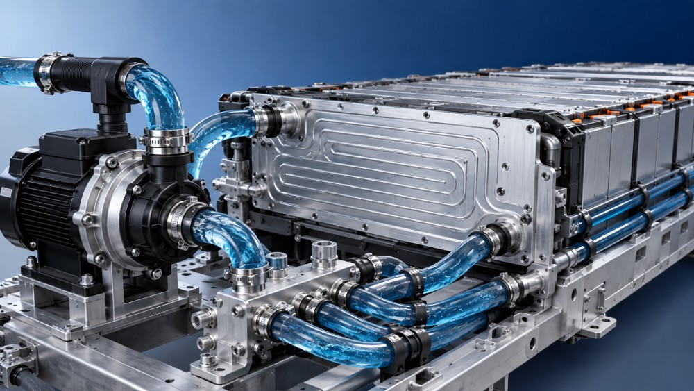
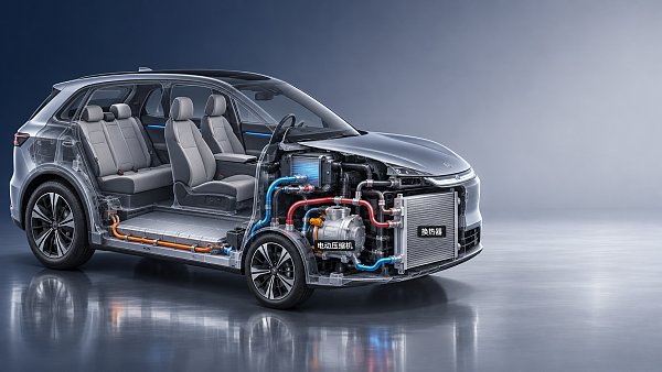
Map the circuit states rather than assuming one hydraulic layout. An integrated thermal valve can direct coolant through a radiator, a chiller, a bypass, or a parallel branch. Some states place the battery and drive-unit circuits in series; others isolate them. The pump must be assessed against every commanded configuration that can occur during charging, propulsion, preconditioning, fault handling, and purge. The highest-pressure condition is not always the highest heat-load condition.
Parallel paths require distribution analysis
Battery modules are often connected through parallel coolant paths. Total loop flow does not confirm that each path receives its intended share. Flow divides according to hydraulic resistance, so unequal hose lengths, manifold port shapes, plate tolerances, or trapped air can starve one branch while the overall pump flow appears acceptable.
For parallel branches, calculate each branch curve and solve for a common pressure drop. The branch with lower resistance takes more flow. If module temperature variation is excessive, increasing pump capacity may have limited effect because the imbalance persists. Reworking manifold geometry, adding calibrated restrictors, changing port orientation, or removing an unintended bypass can produce a more uniform result with less electrical power than fitting a larger pump.
Read pump curves at the intended supply condition
An electric coolant pump curve must be read at the specified voltage, coolant mixture, coolant temperature, and control speed. Published maximum-flow or maximum-head figures are usually endpoints measured separately; they do not describe the usable operating point. Select a pump whose curve crosses the calculated system curve with enough head reserve for production variation, coolant ageing, manufacturing tolerance, and reasonable contamination allowance.
Reserve should be purposeful. Excessive head margin can push the pump into a region where the controller must continually reduce speed, or it can encourage an unnecessarily large motor and higher cost. Too little margin leaves no capacity for a partially loaded filter, increased plate roughness, assembly variation, or a colder-than-nominal coolant condition. The appropriate margin follows the uncertainty in the model and the severity of reduced-flow consequences.
Confirm the pump's allowable inlet pressure and cavitation margin. Cavitation is less likely in a properly pressurized automotive coolant loop than in an open system, yet it can still arise when inlet routing is restrictive, the reservoir placement is poor, local coolant temperature is high, or the pump inlet contains a sharp reducer. Cavitation can sound like intermittent rattling or broadband noise, but similar sounds can result from entrained air. Both conditions reduce hydraulic performance; their corrective actions are different.
Place the pump where inlet conditions remain favorable across vehicle attitude, filling tolerance, and thermal expansion. A reservoir or degas connection should support air separation rather than introduce a persistent gas path toward the impeller. Hose routing that forms high points before the pump, insufficient bleed provisions, and poorly positioned return jets can leave air pockets that appear only after service refill or thermal cycling.
Match control range to the thermal architecture
Most EV battery pumps are electronically controlled, so the selected hardware needs a usable speed range rather than one fixed operating point. At low demand, reduced pump speed lowers electrical consumption and can reduce cabin noise transmitted through the body structure. At high demand, speed authority is needed to recover flow as valves move, coolant thickens, or the thermal system enters a high-restriction chiller route.
Control should use temperature and operating-state information without chasing sensor noise. A pump commanded directly from one outlet temperature can oscillate when transport delay through the cold plate is significant. Battery inlet temperature, outlet temperature, pack temperature spread, coolant temperature at the heat source, and active valve state provide a more reliable basis when interpreted with filtering and rate limits. The control objective is usually temperature regulation and uniformity, not continuous operation at the highest available flow.
Minimum flow also has a thermal purpose. Some cold plates need sufficient velocity to avoid local temperature stratification or to maintain predictable heat-transfer behavior. Other systems can operate at very low flow during steady ambient conditions. The design should establish whether a minimum command is set by heat transfer, air-removal needs, valve actuation, pump electronics, or acoustic stability. These are distinct constraints and should not be merged into an arbitrary minimum-speed value.
Consider electrical, mechanical, and material compatibility together
Pump hydraulic output is only part of auxiliary load. Compare electrical input power at the actual duty points, including controller losses and the effect of voltage variation. A pump that offers a higher peak flow can consume disproportionate energy if it is routinely operated near that region. Because battery thermal management can run during charging and after vehicle shutdown, standby behavior, wake-up logic, and fault-state current draw also belong in the electrical assessment.
Coolant compatibility must cover the impeller, housing, seals, bearing arrangement, adhesive joints, and electrical connector seals. Water-glycol formulations include corrosion inhibitors that can change over service life. Mixed metals in the loop, such as aluminium plates, steel fittings, brass inserts, and stainless elements, make coolant specification and contamination control relevant to pump durability. Elastomer compatibility should be checked against the intended coolant chemistry and temperature exposure rather than assumed from water-only testing.
Installation forces can distort results obtained on a bench. Hose preload, bracket stiffness, vibration paths, connector orientation, and nearby high-voltage harness routing affect serviceability and noise. A pump mounted to a compliant structure may meet acoustic expectations while the same pump on a rigid bracket transmits tonal motor noise into the cabin. Hydraulic pulsation, especially near closed valves or rapid speed changes, can also excite hoses and thin-walled manifolds.
Validate the selected operating points, not only the component rating
Bench validation should measure flow and differential pressure across the pump and, where possible, across the battery branch. Log coolant temperatures at pack inlet and outlet, pressure before and after restrictive elements, pump speed, electrical power, valve position, and air content indicators during fill and thermal cycling. A measured system curve is valuable because it exposes losses missed in nominal CAD geometry, such as connector inserts, hose collapse under vacuum, or a valve whose effective passage is smaller than assumed.
Vehicle-level tests should include the thermal states that change circuit topology. Assess hot charging after a heat soak, sustained propulsion demand, transitions between bypass and heat-rejection paths, low-temperature startup, and refill after service-like draining. Repeated transitions matter because a loop can perform well in a settled condition yet show temporary loss of flow when a valve moves, a pump ramps quickly, or air shifts through the manifold.
When measured temperature non-uniformity remains high, separate hydraulic and thermal causes before increasing pump size. Confirm branch flow balance, purge quality, coolant concentration, plate contact conditions, module assembly pressure, and sensor placement. A larger pump can conceal a distribution defect during early tests while adding power consumption and noise throughout the vehicle life. The preferred pump is the one that reaches the required flow and head across real circuit states, maintains stable controllability, and leaves enough margin for temperature, tolerance, and ageing without relying on permanent over-speed operation.
Have questions about this sector analysis, or seeking best practices specific to your niche? Drop us a line below and let the senior consultants at GAC assist you.
“We respect your privacy. Your information is strictly confidential.”
Related News
- 00
0000-00
How to assess a smart cockpit electronics manufacturer's integration capability - 00
0000-00
How does a shielded HSD cable reduce interference in vehicles? - 00
0000-00
What drives demand for scroll compressors in the automotive market? - 00
0000-00
Does AEC-Q200 apply to flexible printed circuits? - 00
0000-00
How does production volume affect automotive flexible electronics costs?
Weekly Insights
Stay ahead with our curated technology reports delivered every Monday.
Recommended News
 How to assess a smart cockpit electronics manufacturer's integration capabilityAssess a smart cockpit electronics manufacturer's integration capability with practical checks for interfaces, testing, safety, cybersecurity and supplier support.Author:Time:Nov 18, 2026
 How does a shielded HSD cable reduce interference in vehicles?Discover how a shielded HSD cable reduces vehicle interference, and learn why connector design, routing, and testing matter for reliable high-speed data links.Author:Time:Nov 17, 2026
 What drives demand for scroll compressors in the automotive market?Explore the scroll compressor for automobile market and discover how EV adoption, heat pumps, efficiency, and supplier capabilities shape demand.Author:Time:Nov 16, 2026
 Does AEC-Q200 apply to flexible printed circuits?Flexible Printed Circuit AEC-Q200 requirements explained: discover which components qualify and how to assess automotive FPC reliability.Author:Time:Nov 15, 2026
 How does production volume affect automotive flexible electronics costs?Explore how production volume affects automotive flexible electronics cost, from tooling and yield to testing. Compare quotes and negotiate smarter.Author:Time:Nov 14, 2026
 How much does an in-vehicle infotainment system cost to replace?Explore in-vehicle infotainment cost, from affordable repairs to factory replacements. Compare options, installation fees, and compatibility before you buy.Author:Time:Nov 13, 2026
 How does condenser efficiency affect heat pump performance?Discover how condenser high efficiency can improve heat pump performance, reduce compressor power, and boost heating COP—plus the trade-offs to watch.Author:Time:Nov 12, 2026
 What does each FAKRA cable color code mean?FAKRA cable color code explained: Explore common connector colors, typical uses and key compatibility checks before choosing a replacement.Author:Time:Nov 11, 2026
 How to compare noise ratings for battery coolant pumpsCompare coolant pump low noise ratings with confidence. Learn how test conditions, hydraulic duty, tonal noise and installation affect your choice.Author:Time:Nov 10, 2026
 How bright should automotive display systems be in sunlight?Automotive Display Systems need more than brightness to stay readable in sunlight. Discover why 1,000 nits is a starting point and how to evaluate glare and heat.Author:Time:Nov 09, 2026
 How heat pumps improve the efficiency of EV thermal systemsEV Thermal Systems use heat pumps to reduce heating energy demand. Explore how they work, where they excel, and what limits efficiency in cold weather.Author:Time:Nov 08, 2026
 Can a smart cockpit platform support multiple displays?Can a smart cockpit platform support multiple displays? Explore key requirements for performance, safety, connectivity, and supplier evaluation.Author:Time:Nov 07, 2026
 How is automotive connector vibration resistance tested?Automotive connector vibration resistance testing reveals hidden contact failures. Explore test profiles, continuity monitoring and pass criteria.Author:Time:Nov 06, 2026
 How heat pumps save energy in automotive cabin climate systemsAutomotive Cabin Climate Systems energy saving starts with smarter heat pump design. Explore real-world efficiency, cold-weather trade-offs, and testing tips.Author:Time:Nov 05, 2026
 Is an EV heat pump worth it for winter driving range?Is a heat pump worth using in a cold-climate EV? Discover how it affects winter range, when it pays off, and what to check before buying.Author:Time:Nov 04, 2026
 When should you use 50-ohm coaxial cable instead of 75-ohm?Coaxial cable 50 ohm or 75 ohm? Learn when to use each, avoid impedance mismatches, and choose the right cable for reliable RF and video performance.Author:Time:Nov 03, 2026
 How to select a high temperature motor harness for an EVChoose the right high temperature motor harness for your EV. Compare thermal limits, current capacity, shielding, routing, and validation evidence.Author:Time:Nov 02, 2026
 How much does electric power steering replacement cost?Electric power steering price typically ranges from $1,000 to $3,000 for major replacements. Discover cost factors, repair options, and tips for comparing quotes.Author:Time:Nov 01, 2026
 How to size an EV A/C compressor for the required cooling capacitySize an EV A/C Compressor with confidence. Explore cooling loads, performance maps and power limits to select the right compressor for your vehicle.Author:Time:Oct 31, 2026
 How to choose the right pitch for an FPC board connectorFPC board connector pitch affects space, assembly and reliability. Learn how to compare options and select the best fit for your design.Author:Time:Oct 30, 2026
 How zonal design affects harness routing in high-voltage EV architecturesExplore high-voltage electrical architecture zonal design and its impact on EV harness routing. Discover key trade-offs in cable length, safety, thermal performance, and service access.Author:Time:Oct 29, 2026
 How tariffs affect costs in global automotive parts supply chainsNavigate tariffs in the global automotive parts trade supply chain. Learn to compare landed costs, manage duty exposure, and uncover smarter sourcing strategies to protect your margins.Author:Time:Oct 28, 2026
 How to assess vendor lock-in in a software-defined vehicle platformAssess Software-Defined Vehicle platform lock-in with practical tests for API portability, data access, update control, and exit costs. Learn how to choose a platform with a proven exit path.Author:Time:Oct 27, 2026
 How ISO 26262 guides functional safety in steer-by-wire systemsExplore steering systems functional safety through ISO 26262. Learn how hazard analysis, fault-tolerant design, and validation build a stronger steer-by-wire safety case.Author:Time:Oct 26, 2026
 How to evaluate a steering angle sensor manufacturer's accuracy claimsEvaluate steering angle sensor manufacturer accuracy claims with practical checks on calibration, latency, and test evidence. Compare suppliers confidently and avoid costly selection mistakes.Author:Time:Oct 25, 2026
 How to diagnose CAN bus faults in a hybrid vehicle control unitDiagnose Hybrid Vehicle Systems control unit CAN bus faults with step-by-step power, wiring, and waveform checks. Find the root cause and avoid unnecessary replacement.Author:Time:Oct 24, 2026
 How does battery cooling pipe diameter affect coolant pressure drop?Battery Cooling Pipe diameter affects coolant pressure drop and pump power. Explore sizing calculations and practical tips to optimize EV battery cooling and compare options with confidence.Author:Time:Oct 23, 2026
 How to assess PPAP readiness of automotive sensor system manufacturersAssess Automotive Sensor Systems manufacturers for PPAP readiness. Learn to verify production evidence, measurement capability, validation, and traceability to reduce sourcing risks.Author:Time:Oct 22, 2026
 What to ask an FPC connector manufacturer about reliability testingChoosing an FPC Connector manufacturer? Learn what to ask about reliability testing, failure limits, and traceable results to reduce design risks and select with confidence.Author:Time:Oct 21, 2026
 How to verify vehicle fitment for an aftermarket AC evaporatorNavigating the evaporator aftermarket? Verify vehicle fitment with VIN data, OE numbers, and physical interface checks. Use this guide to avoid costly mismatches and order confidently.Author:Time:Oct 20, 2026