How to choose a thermal management controller for battery cooling




How to Choose a Thermal Management Controller for Battery Cooling
Introduction: Choosing a Thermal Management Controller for battery cooling requires more than comparing basic specifications. Technical evaluators must assess control accuracy, sensor and actuator compatibility, communication protocols, functional safety, thermal-load response, and integration with the vehicle’s battery management system.
The right controller improves temperature uniformity, energy efficiency, battery life, and fast-charging performance. It also determines whether a battery cooling architecture can scale across vehicle platforms, climate conditions, and battery pack configurations.
For technical evaluators, the central question is not simply which controller has the most inputs or features. The question is whether it can make stable, safe, efficient decisions under real vehicle operating conditions.
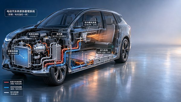
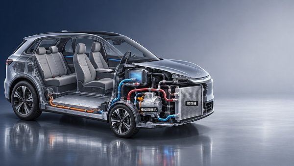
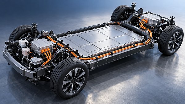
A capable Thermal Management Controller should coordinate battery cooling with heating, cabin conditioning, heat pump operation, charging demand, compressor capacity, valve positions, and battery management system limits.
Start With the Battery Thermal System Requirements
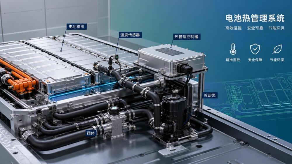
Before selecting hardware, define the thermal system architecture clearly. A controller suitable for a compact passenger EV may be inadequate for a high-power SUV, electric truck, or fast-charging commercial platform.
Review the battery pack’s allowable temperature range, preferred operating window, maximum cell temperature difference, thermal mass, coolant volume, and expected heat generation during driving and charging.
Battery cooling requirements change significantly between normal cruising, regenerative braking, repeated acceleration, high ambient temperature operation, and DC fast charging. The controller must manage transitions without overshoot or unstable cycling.
Technical teams should identify whether the system uses direct liquid cooling, refrigerant-assisted cooling, a chiller loop, a heat pump loop, or an integrated multi-loop thermal architecture.
The more integrated the vehicle thermal system becomes, the more valuable coordinated control becomes. A controller must understand how battery cooling decisions affect cabin comfort, compressor load, and overall energy consumption.
Define performance targets using measurable conditions. Examples include coolant outlet temperature control, battery temperature uniformity, cooling response time, compressor power, pump speed stability, and charging derating prevention.
A controller should be evaluated against actual system requirements instead of generic feature lists. This approach prevents over-specification while reducing the risk of selecting an underpowered control platform.
Evaluate Control Accuracy and Response Under Dynamic Loads
Control accuracy is a primary selection factor because battery cooling depends on maintaining stable temperatures rather than simply activating components when a threshold is exceeded.
Look for support for advanced control strategies such as PID control, feedforward logic, map-based calibration, state machines, predictive functions, and adaptive control where system complexity justifies them.
A basic threshold controller may work for a simple coolant loop. However, it can create temperature oscillation, unnecessary compressor cycling, excessive pump noise, and avoidable electrical energy consumption.
Fast charging creates one of the most demanding scenarios. The Thermal Management Controller should anticipate rising battery heat rather than react only after cells approach their temperature limit.
Feedforward control can use charging current, battery state of charge, cell temperature, ambient conditions, and predicted heat load to begin cooling earlier and reduce delayed response.
Assess the controller’s sampling rate, processing capability, output resolution, and actuator command update speed. Slow control loops can be problematic when chiller capacity or compressor speed must change quickly.
Validation should include transient tests, not only steady-state bench tests. Confirm performance during abrupt charging changes, rapid ambient shifts, stop-and-go traffic, hill climbing, and repeated high-power events.
Confirm Sensor Inputs and Actuator Output Compatibility
Sensor and actuator compatibility is often underestimated during controller selection. Integration problems commonly arise when electrical interfaces, signal types, diagnostics, or accuracy requirements are reviewed too late.
Typical battery cooling systems use coolant temperature sensors, pressure sensors, flow sensors, battery temperature data, ambient sensors, refrigerant sensors, humidity signals, and compressor feedback.
Determine whether the controller accepts analog voltage, resistance-based temperature signals, frequency signals, SENT, LIN, CAN, PWM, or digitally transmitted sensor data from other vehicle controllers.
Sensor accuracy should match control objectives. If battery temperature uniformity targets are tight, weak sensor precision, poor placement, or inconsistent signal filtering can undermine otherwise capable control software.
Review available outputs for electric coolant pumps, coolant valves, electronic expansion valves, compressors, fans, PTC heaters, chiller valves, and bypass actuators.
Output types matter. PWM, LIN, CAN, high-side switching, low-side switching, and motor-control interfaces require different electrical designs, protection methods, diagnostics, and calibration processes.
Ask suppliers for a complete input-output matrix early. It should include voltage ranges, current capacity, fault detection, wake-up behavior, short-circuit protection, and default behavior after communication loss.
Assess Integration With the Battery Management System
The Thermal Management Controller cannot be evaluated independently from the battery management system. The BMS provides essential information that determines when cooling, heating, derating, or protection actions are required.
At minimum, the controller should receive battery temperature, state of charge, current, voltage, power limits, charging status, insulation status where relevant, and battery fault information.
In return, the controller may need to report coolant conditions, thermal system status, available cooling capacity, actuator faults, estimated thermal capability, and active limitation requests.
Clarify control ownership between the BMS and thermal controller. Ambiguous authority can create conflicts, such as one ECU requesting maximum cooling while another disables compressor operation for energy-saving logic.
A practical architecture defines clear command priorities. Safety limits, battery protection, fault responses, charging permissions, cabin comfort, energy optimization, and component protection should follow documented hierarchy rules.
Check whether the controller supports configurable interfaces for different BMS suppliers. This is especially important for OEMs and Tier 1 suppliers managing multiple vehicle programs or battery sources.
Integration testing should include communication loss, invalid temperature signals, conflicting commands, delayed BMS messages, battery replacement scenarios, and software version mismatches across connected ECUs.
Review Vehicle Communication Protocols and Diagnostic Capability
Communication compatibility affects both system performance and program timing. A controller must fit the vehicle’s electrical and electronic architecture without requiring unnecessary gateway work or custom protocol development.
CAN remains common in thermal control applications, but CAN FD, LIN, Automotive Ethernet, and domain-controller communication may also be required in newer EV platforms.
Confirm supported baud rates, message timing, network-management behavior, wake-up functions, sleep current, diagnostic transport protocols, and compatibility with the vehicle’s cybersecurity architecture.
For distributed thermal systems, network timing becomes important. Delayed data from compressors, pumps, valves, HVAC controllers, or BMS modules can affect control stability and fault response.
Diagnostic capability should extend beyond simple error reporting. Engineers need access to sensor plausibility checks, actuator feedback, fault counters, freeze-frame records, calibration values, and communication status.
Consider whether the controller supports UDS diagnostics, DTC management, end-of-line programming, software flashing, secure boot, and remote update processes required by the vehicle program.
Good diagnostics reduce commissioning time and improve serviceability. They also help warranty teams distinguish between controller faults, component failures, incorrect calibration, coolant issues, and system-level integration problems.
Do Not Treat Functional Safety as a Documentation Exercise
Battery thermal management is directly connected to battery safety, charging availability, vehicle performance, and component protection. Functional safety requirements should therefore influence both controller design and system architecture.
Determine the applicable safety goals before comparing suppliers. These may include preventing battery overheating, detecting sensor failure, avoiding unintended heating, managing lost communication, and limiting component operation during faults.
ISO 26262 capability should be assessed at the relevant system level. A supplier’s general safety statement is insufficient without evidence for the intended application, interfaces, and assigned safety requirements.
Review hardware safety mechanisms such as watchdogs, voltage monitoring, output monitoring, redundant sensing support, memory protection, controlled shutdown, and fault-tolerant communication behavior.
Software safety mechanisms matter equally. The controller should detect implausible values, stuck actuators, failed pumps, abnormal pressure, excessive compressor demand, and inconsistent thermal-model results.
Fail-safe behavior must be defined by scenario. For example, a failed temperature sensor may require conservative cooling, power limitation requests, charging inhibition, or a controlled transition to a degraded mode.
Ask for safety work products that match the program stage. These may include safety manuals, assumptions of use, FMEDA summaries, diagnostic coverage information, and integration responsibilities for the vehicle manufacturer.
Compare Energy Efficiency Across Whole-Vehicle Operating Modes
Battery cooling performance cannot be separated from energy efficiency. Excessive compressor operation, unnecessary coolant pumping, and poor valve control can reduce driving range and increase system wear.
An effective Thermal Management Controller balances thermal protection with electrical consumption. It should use only the cooling capacity required to maintain battery performance and avoid overly aggressive component commands.
Evaluate how the controller coordinates battery cooling with cabin HVAC demand. In an integrated heat pump system, shared components can create tradeoffs between occupant comfort and battery temperature control.
Look for operating modes that exploit favorable conditions. Ambient air cooling, passive heat rejection, heat recovery, coolant-loop bypassing, and reduced pump speed can lower energy use in appropriate climates.
The controller should also account for low-temperature operation. Battery heating, heat pump availability, compressor protection, coolant viscosity, and charging readiness must be managed without unnecessary energy loss.
Use drive-cycle and charging-cycle simulations to compare energy demand. Bench efficiency figures are useful, but vehicle-level analysis better reveals the impact on range, charging time, and customer experience.
For global vehicle programs, assess calibration flexibility by market. Hot climates, cold regions, high-altitude conditions, traffic density, and charging infrastructure availability all affect thermal energy strategies.
Verify Software, Calibration, and Validation Support
Controller hardware is only part of the decision. Battery cooling performance depends heavily on embedded software quality, calibration access, model validation, and the supplier’s ability to support program changes.
Clarify whether the supplier delivers fixed application software, configurable logic, source-code access, calibration tools, model-based development support, or co-development services with the OEM or Tier 1 team.
Calibration ownership should be agreed early. Teams need practical access to thresholds, maps, control gains, fault limits, actuator limits, thermal targets, and regional operating strategies.
Ask how software changes are tested and released. A disciplined process should include requirements traceability, MIL, SIL, HIL testing, vehicle validation, regression testing, and controlled version management.
HIL testing is particularly valuable because it can simulate sensor faults, thermal disturbances, communication delays, actuator failures, and charging events before vehicles are available in large numbers.
Supplier support should include system engineering, calibration guidance, diagnostic documentation, test assistance, and root-cause analysis. These capabilities often matter more than small differences in unit price.
Technical evaluators should request representative test evidence. Useful material includes control response plots, fault reaction timing, thermal cycling results, electromagnetic compatibility data, and vehicle-level validation summaries.
Use a Structured Selection Process Before Nomination
A structured evaluation process helps teams compare controllers consistently and prevents purchasing decisions from being driven by isolated specifications or incomplete supplier presentations.
Start with a requirements matrix covering thermal performance, inputs, outputs, communication, diagnostics, safety, cybersecurity, environmental durability, packaging, software, validation, cost, and supply continuity.
Assign weighted scores according to program priorities. A performance EV with fast-charging requirements may emphasize transient cooling and functional safety, while a fleet vehicle may prioritize durability and service diagnostics.
Request application-specific demonstrations rather than generic product introductions. Suppliers should show how their controller manages the actual coolant loops, actuators, battery signals, and operating modes under consideration.
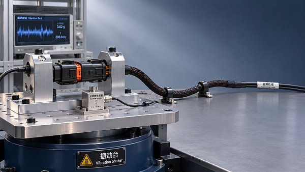
Review environmental specifications carefully. Automotive controllers may face vibration, thermal cycling, water exposure, corrosion risk, voltage transients, electromagnetic interference, and long operating life requirements.
Supply-chain factors also deserve attention. Confirm manufacturing location, semiconductor sourcing, lifecycle management, alternate component strategy, change notification procedures, and regional technical support availability.
Finally, validate the selected Thermal Management Controller in a representative vehicle environment. A successful nomination should be supported by evidence from simulation, bench testing, HIL testing, and on-road operation.
Conclusion: Select for System Behavior, Not Isolated Specifications
The best Thermal Management Controller is the one that supports stable battery temperatures, efficient energy use, safe fault handling, and reliable integration with the BMS and broader vehicle thermal architecture.
Technical evaluators should prioritize real operating behavior over marketing claims. Control response, interface compatibility, diagnostics, safety mechanisms, software maturity, and validation evidence are the most meaningful decision criteria.
A controller that fits current requirements but cannot accommodate new battery chemistries, higher charging power, integrated heat pump functions, or regional calibration needs may create expensive future limitations.
By defining system requirements first and validating suppliers through realistic use cases, engineering teams can select a thermal control solution that protects battery performance throughout the vehicle lifecycle.
Have questions about this sector analysis, or seeking best practices specific to your niche? Drop us a line below and let the senior consultants at GAC assist you.
“We respect your privacy. Your information is strictly confidential.”
Related News
- 00
0000-00
How to assess a smart cockpit electronics manufacturer's integration capability - 00
0000-00
How does a shielded HSD cable reduce interference in vehicles? - 00
0000-00
What drives demand for scroll compressors in the automotive market? - 00
0000-00
Does AEC-Q200 apply to flexible printed circuits? - 00
0000-00
How does production volume affect automotive flexible electronics costs?
Weekly Insights
Stay ahead with our curated technology reports delivered every Monday.
Recommended News
 How to assess a smart cockpit electronics manufacturer's integration capabilityAssess a smart cockpit electronics manufacturer's integration capability with practical checks for interfaces, testing, safety, cybersecurity and supplier support.Author:Time:Nov 18, 2026
 How does a shielded HSD cable reduce interference in vehicles?Discover how a shielded HSD cable reduces vehicle interference, and learn why connector design, routing, and testing matter for reliable high-speed data links.Author:Time:Nov 17, 2026
 What drives demand for scroll compressors in the automotive market?Explore the scroll compressor for automobile market and discover how EV adoption, heat pumps, efficiency, and supplier capabilities shape demand.Author:Time:Nov 16, 2026
 Does AEC-Q200 apply to flexible printed circuits?Flexible Printed Circuit AEC-Q200 requirements explained: discover which components qualify and how to assess automotive FPC reliability.Author:Time:Nov 15, 2026
 How does production volume affect automotive flexible electronics costs?Explore how production volume affects automotive flexible electronics cost, from tooling and yield to testing. Compare quotes and negotiate smarter.Author:Time:Nov 14, 2026
 How much does an in-vehicle infotainment system cost to replace?Explore in-vehicle infotainment cost, from affordable repairs to factory replacements. Compare options, installation fees, and compatibility before you buy.Author:Time:Nov 13, 2026
 How does condenser efficiency affect heat pump performance?Discover how condenser high efficiency can improve heat pump performance, reduce compressor power, and boost heating COP—plus the trade-offs to watch.Author:Time:Nov 12, 2026
 What does each FAKRA cable color code mean?FAKRA cable color code explained: Explore common connector colors, typical uses and key compatibility checks before choosing a replacement.Author:Time:Nov 11, 2026
 How to compare noise ratings for battery coolant pumpsCompare coolant pump low noise ratings with confidence. Learn how test conditions, hydraulic duty, tonal noise and installation affect your choice.Author:Time:Nov 10, 2026
 How bright should automotive display systems be in sunlight?Automotive Display Systems need more than brightness to stay readable in sunlight. Discover why 1,000 nits is a starting point and how to evaluate glare and heat.Author:Time:Nov 09, 2026
 How heat pumps improve the efficiency of EV thermal systemsEV Thermal Systems use heat pumps to reduce heating energy demand. Explore how they work, where they excel, and what limits efficiency in cold weather.Author:Time:Nov 08, 2026
 Can a smart cockpit platform support multiple displays?Can a smart cockpit platform support multiple displays? Explore key requirements for performance, safety, connectivity, and supplier evaluation.Author:Time:Nov 07, 2026
 How is automotive connector vibration resistance tested?Automotive connector vibration resistance testing reveals hidden contact failures. Explore test profiles, continuity monitoring and pass criteria.Author:Time:Nov 06, 2026
 How heat pumps save energy in automotive cabin climate systemsAutomotive Cabin Climate Systems energy saving starts with smarter heat pump design. Explore real-world efficiency, cold-weather trade-offs, and testing tips.Author:Time:Nov 05, 2026
 Is an EV heat pump worth it for winter driving range?Is a heat pump worth using in a cold-climate EV? Discover how it affects winter range, when it pays off, and what to check before buying.Author:Time:Nov 04, 2026
 When should you use 50-ohm coaxial cable instead of 75-ohm?Coaxial cable 50 ohm or 75 ohm? Learn when to use each, avoid impedance mismatches, and choose the right cable for reliable RF and video performance.Author:Time:Nov 03, 2026
 How to select a high temperature motor harness for an EVChoose the right high temperature motor harness for your EV. Compare thermal limits, current capacity, shielding, routing, and validation evidence.Author:Time:Nov 02, 2026
 How much does electric power steering replacement cost?Electric power steering price typically ranges from $1,000 to $3,000 for major replacements. Discover cost factors, repair options, and tips for comparing quotes.Author:Time:Nov 01, 2026
 How to size an EV A/C compressor for the required cooling capacitySize an EV A/C Compressor with confidence. Explore cooling loads, performance maps and power limits to select the right compressor for your vehicle.Author:Time:Oct 31, 2026
 How to choose the right pitch for an FPC board connectorFPC board connector pitch affects space, assembly and reliability. Learn how to compare options and select the best fit for your design.Author:Time:Oct 30, 2026
 How zonal design affects harness routing in high-voltage EV architecturesExplore high-voltage electrical architecture zonal design and its impact on EV harness routing. Discover key trade-offs in cable length, safety, thermal performance, and service access.Author:Time:Oct 29, 2026
 How tariffs affect costs in global automotive parts supply chainsNavigate tariffs in the global automotive parts trade supply chain. Learn to compare landed costs, manage duty exposure, and uncover smarter sourcing strategies to protect your margins.Author:Time:Oct 28, 2026
 How to assess vendor lock-in in a software-defined vehicle platformAssess Software-Defined Vehicle platform lock-in with practical tests for API portability, data access, update control, and exit costs. Learn how to choose a platform with a proven exit path.Author:Time:Oct 27, 2026
 How ISO 26262 guides functional safety in steer-by-wire systemsExplore steering systems functional safety through ISO 26262. Learn how hazard analysis, fault-tolerant design, and validation build a stronger steer-by-wire safety case.Author:Time:Oct 26, 2026
 How to evaluate a steering angle sensor manufacturer's accuracy claimsEvaluate steering angle sensor manufacturer accuracy claims with practical checks on calibration, latency, and test evidence. Compare suppliers confidently and avoid costly selection mistakes.Author:Time:Oct 25, 2026
 How to diagnose CAN bus faults in a hybrid vehicle control unitDiagnose Hybrid Vehicle Systems control unit CAN bus faults with step-by-step power, wiring, and waveform checks. Find the root cause and avoid unnecessary replacement.Author:Time:Oct 24, 2026
 How does battery cooling pipe diameter affect coolant pressure drop?Battery Cooling Pipe diameter affects coolant pressure drop and pump power. Explore sizing calculations and practical tips to optimize EV battery cooling and compare options with confidence.Author:Time:Oct 23, 2026
 How to assess PPAP readiness of automotive sensor system manufacturersAssess Automotive Sensor Systems manufacturers for PPAP readiness. Learn to verify production evidence, measurement capability, validation, and traceability to reduce sourcing risks.Author:Time:Oct 22, 2026
 What to ask an FPC connector manufacturer about reliability testingChoosing an FPC Connector manufacturer? Learn what to ask about reliability testing, failure limits, and traceable results to reduce design risks and select with confidence.Author:Time:Oct 21, 2026
 How to verify vehicle fitment for an aftermarket AC evaporatorNavigating the evaporator aftermarket? Verify vehicle fitment with VIN data, OE numbers, and physical interface checks. Use this guide to avoid costly mismatches and order confidently.Author:Time:Oct 20, 2026