How Thermal Management Integration Affects EV Battery Cooling Efficiency




Start with the thermal architecture, not the cooling plate
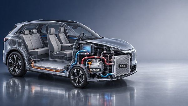
When technical teams compare EV battery cooling solutions, they often jump straight to the cold plate, coolant flow rate, or cell temperature spread. That is too narrow. Cooling efficiency is shaped much earlier, at system architecture level, where valves, pumps, refrigerant loops, battery circuits, cabin loads, and control logic are tied together. The practical question is not whether a battery liquid cooling system exists. The question is how well the full thermal management integration keeps the battery inside its usable temperature window without wasting energy or creating avoidable reliability risks.
For a technical evaluator, this is usually where weak designs reveal themselves. A system can look good in a component datasheet and still perform poorly once heat pump operation, cabin conditioning, fast charging, and low-ambient startup all compete for the same thermal resources. The checklist below is built for that real comparison work.
Check whether the integration goal is clear
Before reviewing hardware, pin down what the system is trying to optimize. Integrated thermal designs usually balance several targets at once:
- cell temperature uniformity during drive and charge,
- preconditioning speed before DC fast charging,
- heat pump efficiency in cold weather,
- parasitic power consumption from pumps, valves, and compressors,
- pack protection during sustained high load or repeated charging events.
If the architecture tries to optimize everything equally, it usually ends up making compromises that are hidden until validation. Ask for the operating cases used to size the system. Not marketing use cases, but engineering ones: repeated fast charge, hill climb in high ambient, winter cabin heating with a cold-soaked pack, and mixed urban duty with frequent stops. A design that is efficient in one case but unstable across the others is not well integrated.
Map the full heat path and count every transfer step
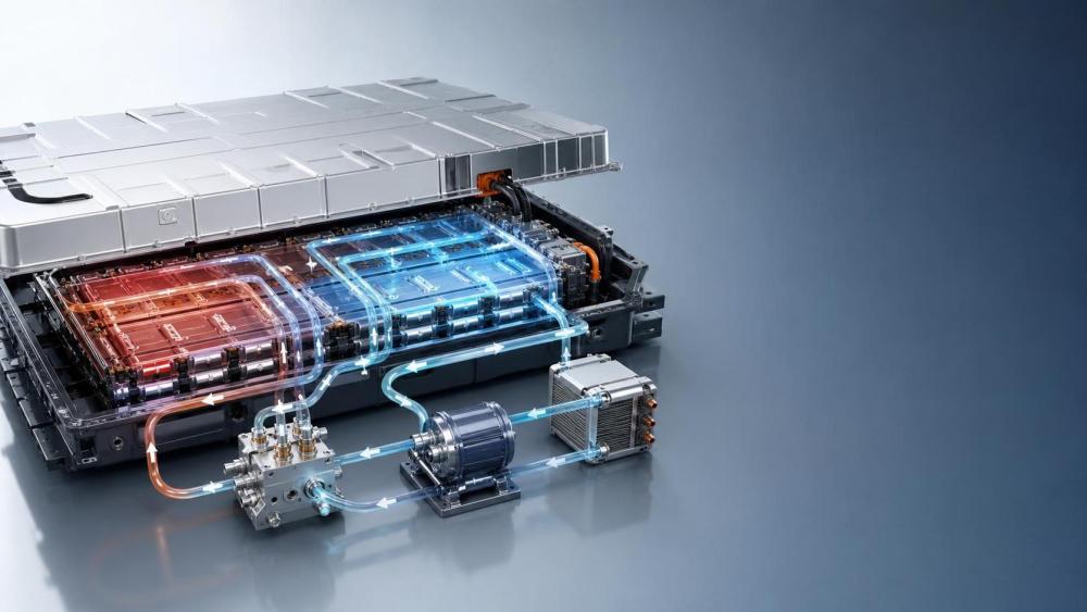
A simple way to judge thermal management integration is to trace where battery heat goes, and how many interfaces it crosses before it is rejected or reused. Every extra transfer step adds temperature difference, control delay, and loss.
For example, a battery may reject heat to a liquid loop, then to a chiller, then into the refrigerant side, then finally to ambient. Another architecture may allow some heat recovery for cabin conditioning or pack warm-up. Integration helps when those paths are short, purposeful, and controllable. It hurts when the system adds complexity without reducing energy use or thermal lag.
A quick review point: if multiple loops exist, identify which heat exchangers are always in the path and which are bypassable. Systems with intelligent bypass control often outperform more complicated layouts that force coolant through unnecessary branches.
Look closely at valves, because integration usually succeeds or fails there
Integrated thermal valves do more than route flow. They define mode switching speed, pressure loss, cross-loop isolation, and failure behavior. A battery cooling loop can be well designed on paper and still lose efficiency because the valve arrangement creates sluggish transitions between cooling, heating, bypass, and heat recovery modes.
Check these points in detail:
- Whether valve positions allow a true bypass path or only a partial one.
- Whether the control strategy prevents simultaneous unwanted heat exchange between battery and cabin circuits.
- How the system behaves during a stuck valve condition, including default thermal protection mode.
- Whether pressure drop across the integrated valve block forces the pump to work harder in common operating modes.
One common mistake is treating valve integration as packaging optimization only. Compactness matters, but if the valve block adds hydraulic resistance or makes service isolation difficult, battery cooling efficiency may decline even though the assembly looks more advanced.
Do not evaluate coolant flow in isolation
Higher coolant flow does not automatically mean better battery cooling. In an integrated system, useful flow depends on plate design, channel geometry, pump control range, and temperature approach across the heat exchanger network. If the flow increase mainly offsets poor hydraulic layout, the electrical penalty may outweigh the thermal gain.
Ask for the relationship between pump power and battery temperature control under representative duty cycles. What you want to see is not just maximum cooling capacity, but how much electrical overhead is required to maintain pack uniformity when the vehicle is operating near thermal limits. That is where thermal management integration becomes measurable rather than conceptual.
Separate steady-state performance from transient behavior
Many systems look acceptable at steady state. The harder question is what happens during transitions: fast-charge entry, compressor ramp-up, low-temperature startup, or a sudden increase in discharge load. Integrated systems are judged by how quickly they move from one thermal mode to another without overshoot, oscillation, or temporary hot spots.
Review mode transition logic alongside thermal hardware. If the battery loop, heat pump, and cabin circuit all depend on centralized control, the software calibration becomes part of cooling efficiency. Slow actuator response, unstable sensor filtering, or conservative fault handling can waste thermal potential that the hardware should have delivered.
Check how the battery competes with cabin and power electronics loads
In real vehicles, the battery is rarely the only thermal priority. Cabin comfort, inverter cooling, e-motor heat rejection, and defrost demand can all pull on the same refrigerant or coolant resources. This is one of the biggest reasons integrated systems are hard to compare from component descriptions alone.
When you assess an architecture, ask which loads are prioritized in each operating mode and what the control system sacrifices when demand exceeds available capacity. If battery cooling performance depends on reducing cabin load first, that tradeoff should be explicit. If it is hidden, the pack may appear thermally robust in lab conditions but drift out of target temperature range in customer use.
Review the low-temperature strategy with the same rigor as hot-weather cooling
Battery cooling efficiency is often discussed as a hot-weather issue, but integration quality shows up just as clearly in cold conditions. A pack that cannot be warmed efficiently before charging or high-power discharge loses usable performance even if the summer cooling loop is strong.
For cold-weather evaluation, check:
- whether the heat pump can contribute directly or indirectly to battery preheating,
- how much of the loop must be warmed before heat reaches the cells,
- whether valves isolate cold thermal mass effectively,
- how the control logic balances charging readiness against energy consumption.
A design with elegant heat recovery on paper can still be slow in winter because too much coolant volume must be conditioned before the battery sees any benefit.
Use a practical comparison table during architecture review
Check the sensing layout before trusting the control claims
Integrated control is only as good as the sensing behind it. If temperature sensors are sparse, slow, or placed where they mainly reflect coolant rather than cell behavior, the control algorithm may respond too late. That can lead to overcooling, undercooling, or uneven pack conditioning.
For technical evaluation, review sensor placement relative to the thermal bottlenecks: pack inlet and outlet, critical module regions, refrigerant-coolant interface, and any branch where blended flow is possible. Then check whether the controller acts on direct measurement, estimation, or a combined model. Model-based control can work well, but only if the assumptions still hold across aging, contamination, and off-design operation.
Treat reliability as part of efficiency
This is where many reviews become too theoretical. A thermal layout that is efficient when new but sensitive to valve drift, trapped air, coolant contamination, or refrigerant-side degradation will not stay efficient in the field. For battery systems, real cooling efficiency is lifecycle efficiency.
Look for design choices that reduce long-term variation: serviceable fill and bleed strategy, stable actuator design, clear isolation between loops where contamination risk exists, and control fallback modes that preserve pack protection when one subsystem is degraded. If the architecture has multiple tightly coupled components, ask whether failure in one branch forces the whole thermal system into a low-performance mode.
Tie the review back to standards and validation evidence
For a technical or standards-driven search, broad claims are not enough. The review should end in a document check. Verify which engineering specifications define battery temperature limits, charging precondition targets, coolant characteristics, and fault responses. Then make sure the system architecture and test plan use the same boundaries. A lot of confusion comes from comparing one supplier’s thermal concept against another supplier’s test case, with different ambient assumptions and different battery operating windows.
When standards or program requirements vary by platform, focus on the exact fields that affect the conclusion: operating temperature window, maximum allowable cell gradient, charge-related preconditioning requirement, coolant compatibility, and failure response definition. Those are the items that determine whether thermal management integration is genuinely improving EV battery cooling efficiency or simply moving thermal load around the vehicle.
A workable review order
If you need a practical sequence, use this one. Start with architecture intent and operating cases. Then map heat paths, review valve logic, and check where pressure loss is introduced. After that, compare transient behavior, not just steady-state cooling. Bring in load competition between battery, cabin, and e-drive. Finish with sensor placement, fault handling, and the documents that define acceptance criteria.
That order tends to expose the real tradeoffs early. It also keeps the evaluation grounded in how the vehicle will actually behave, which is the only place thermal management integration really proves its value.
Have questions about this sector analysis, or seeking best practices specific to your niche? Drop us a line below and let the senior consultants at GAC assist you.
“We respect your privacy. Your information is strictly confidential.”
Related News
- 00
0000-00
How to assess a smart cockpit electronics manufacturer's integration capability - 00
0000-00
How does a shielded HSD cable reduce interference in vehicles? - 00
0000-00
What drives demand for scroll compressors in the automotive market? - 00
0000-00
Does AEC-Q200 apply to flexible printed circuits? - 00
0000-00
How does production volume affect automotive flexible electronics costs?
Weekly Insights
Stay ahead with our curated technology reports delivered every Monday.
Recommended News
 How to assess a smart cockpit electronics manufacturer's integration capabilityAssess a smart cockpit electronics manufacturer's integration capability with practical checks for interfaces, testing, safety, cybersecurity and supplier support.Author:Time:Nov 18, 2026
 How does a shielded HSD cable reduce interference in vehicles?Discover how a shielded HSD cable reduces vehicle interference, and learn why connector design, routing, and testing matter for reliable high-speed data links.Author:Time:Nov 17, 2026
 What drives demand for scroll compressors in the automotive market?Explore the scroll compressor for automobile market and discover how EV adoption, heat pumps, efficiency, and supplier capabilities shape demand.Author:Time:Nov 16, 2026
 Does AEC-Q200 apply to flexible printed circuits?Flexible Printed Circuit AEC-Q200 requirements explained: discover which components qualify and how to assess automotive FPC reliability.Author:Time:Nov 15, 2026
 How does production volume affect automotive flexible electronics costs?Explore how production volume affects automotive flexible electronics cost, from tooling and yield to testing. Compare quotes and negotiate smarter.Author:Time:Nov 14, 2026
 How much does an in-vehicle infotainment system cost to replace?Explore in-vehicle infotainment cost, from affordable repairs to factory replacements. Compare options, installation fees, and compatibility before you buy.Author:Time:Nov 13, 2026
 How does condenser efficiency affect heat pump performance?Discover how condenser high efficiency can improve heat pump performance, reduce compressor power, and boost heating COP—plus the trade-offs to watch.Author:Time:Nov 12, 2026
 What does each FAKRA cable color code mean?FAKRA cable color code explained: Explore common connector colors, typical uses and key compatibility checks before choosing a replacement.Author:Time:Nov 11, 2026
 How to compare noise ratings for battery coolant pumpsCompare coolant pump low noise ratings with confidence. Learn how test conditions, hydraulic duty, tonal noise and installation affect your choice.Author:Time:Nov 10, 2026
 How bright should automotive display systems be in sunlight?Automotive Display Systems need more than brightness to stay readable in sunlight. Discover why 1,000 nits is a starting point and how to evaluate glare and heat.Author:Time:Nov 09, 2026
 How heat pumps improve the efficiency of EV thermal systemsEV Thermal Systems use heat pumps to reduce heating energy demand. Explore how they work, where they excel, and what limits efficiency in cold weather.Author:Time:Nov 08, 2026
 Can a smart cockpit platform support multiple displays?Can a smart cockpit platform support multiple displays? Explore key requirements for performance, safety, connectivity, and supplier evaluation.Author:Time:Nov 07, 2026
 How is automotive connector vibration resistance tested?Automotive connector vibration resistance testing reveals hidden contact failures. Explore test profiles, continuity monitoring and pass criteria.Author:Time:Nov 06, 2026
 How heat pumps save energy in automotive cabin climate systemsAutomotive Cabin Climate Systems energy saving starts with smarter heat pump design. Explore real-world efficiency, cold-weather trade-offs, and testing tips.Author:Time:Nov 05, 2026
 Is an EV heat pump worth it for winter driving range?Is a heat pump worth using in a cold-climate EV? Discover how it affects winter range, when it pays off, and what to check before buying.Author:Time:Nov 04, 2026
 When should you use 50-ohm coaxial cable instead of 75-ohm?Coaxial cable 50 ohm or 75 ohm? Learn when to use each, avoid impedance mismatches, and choose the right cable for reliable RF and video performance.Author:Time:Nov 03, 2026
 How to select a high temperature motor harness for an EVChoose the right high temperature motor harness for your EV. Compare thermal limits, current capacity, shielding, routing, and validation evidence.Author:Time:Nov 02, 2026
 How much does electric power steering replacement cost?Electric power steering price typically ranges from $1,000 to $3,000 for major replacements. Discover cost factors, repair options, and tips for comparing quotes.Author:Time:Nov 01, 2026
 How to size an EV A/C compressor for the required cooling capacitySize an EV A/C Compressor with confidence. Explore cooling loads, performance maps and power limits to select the right compressor for your vehicle.Author:Time:Oct 31, 2026
 How to choose the right pitch for an FPC board connectorFPC board connector pitch affects space, assembly and reliability. Learn how to compare options and select the best fit for your design.Author:Time:Oct 30, 2026
 How zonal design affects harness routing in high-voltage EV architecturesExplore high-voltage electrical architecture zonal design and its impact on EV harness routing. Discover key trade-offs in cable length, safety, thermal performance, and service access.Author:Time:Oct 29, 2026
 How tariffs affect costs in global automotive parts supply chainsNavigate tariffs in the global automotive parts trade supply chain. Learn to compare landed costs, manage duty exposure, and uncover smarter sourcing strategies to protect your margins.Author:Time:Oct 28, 2026
 How to assess vendor lock-in in a software-defined vehicle platformAssess Software-Defined Vehicle platform lock-in with practical tests for API portability, data access, update control, and exit costs. Learn how to choose a platform with a proven exit path.Author:Time:Oct 27, 2026
 How ISO 26262 guides functional safety in steer-by-wire systemsExplore steering systems functional safety through ISO 26262. Learn how hazard analysis, fault-tolerant design, and validation build a stronger steer-by-wire safety case.Author:Time:Oct 26, 2026
 How to evaluate a steering angle sensor manufacturer's accuracy claimsEvaluate steering angle sensor manufacturer accuracy claims with practical checks on calibration, latency, and test evidence. Compare suppliers confidently and avoid costly selection mistakes.Author:Time:Oct 25, 2026
 How to diagnose CAN bus faults in a hybrid vehicle control unitDiagnose Hybrid Vehicle Systems control unit CAN bus faults with step-by-step power, wiring, and waveform checks. Find the root cause and avoid unnecessary replacement.Author:Time:Oct 24, 2026
 How does battery cooling pipe diameter affect coolant pressure drop?Battery Cooling Pipe diameter affects coolant pressure drop and pump power. Explore sizing calculations and practical tips to optimize EV battery cooling and compare options with confidence.Author:Time:Oct 23, 2026
 How to assess PPAP readiness of automotive sensor system manufacturersAssess Automotive Sensor Systems manufacturers for PPAP readiness. Learn to verify production evidence, measurement capability, validation, and traceability to reduce sourcing risks.Author:Time:Oct 22, 2026
 What to ask an FPC connector manufacturer about reliability testingChoosing an FPC Connector manufacturer? Learn what to ask about reliability testing, failure limits, and traceable results to reduce design risks and select with confidence.Author:Time:Oct 21, 2026
 How to verify vehicle fitment for an aftermarket AC evaporatorNavigating the evaporator aftermarket? Verify vehicle fitment with VIN data, OE numbers, and physical interface checks. Use this guide to avoid costly mismatches and order confidently.Author:Time:Oct 20, 2026