Fluid Dynamics Mistakes That Lead to Costly Thermal Redesigns




In automotive thermal programs, small fluid dynamics mistakes can trigger major redesign costs, delayed validation, and compromised system efficiency. For project managers and engineering leads, understanding where flow behavior, pressure drop, and heat transfer assumptions go wrong is critical to avoiding late-stage surprises. This article highlights the most common pitfalls behind costly thermal redesigns and how smarter cross-functional decisions can protect timelines, budgets, and product performance.
Why fluid dynamics errors become program-level risks in automotive thermal development
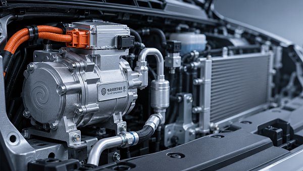
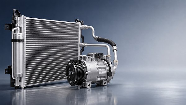
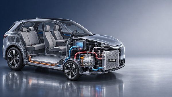
For project leaders, fluid dynamics is not just a simulation topic. It directly affects cooling loop architecture, pump sizing, refrigerant routing, valve response, NVH performance, packaging feasibility, and downstream validation. In NEV thermal management systems, a poor flow assumption in the concept phase can cascade into hardware changes across e-compressors, heat exchangers, battery plates, hoses, manifolds, and control logic.
This is why costly redesigns often appear late. The original issue may start as a minor mismatch between expected and real flow behavior, but the impact reaches prototype tooling, supplier coordination, software calibration, and test schedules. For teams managing electrified platforms, fluid dynamics mistakes now carry more risk because thermal systems are more integrated than in conventional vehicles.
- Battery, cabin, and e-drive loops increasingly share components, making one flow imbalance affect multiple subsystems.
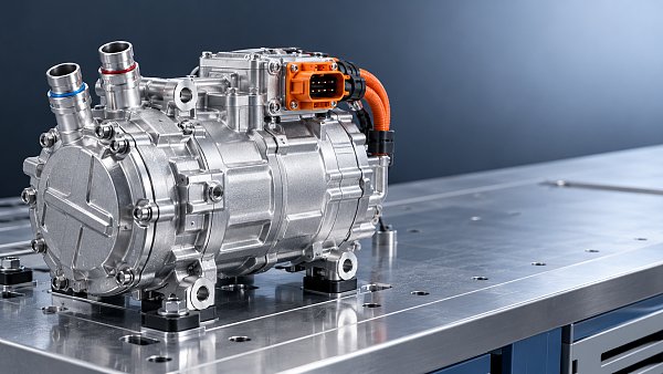
- Electric compressors and heat pumps are sensitive to pressure drop, oil return, and transient operating conditions.
- High integration reduces physical margin, so minor fluid dynamics errors are less forgiving during packaging and validation.
GACT tracks these interactions across auto A/C compressors, NEV thermal management systems, smart cabin electronics, and related electromechanical controls. That system-level perspective matters because project decisions rarely fail due to one isolated component. They fail when fluid, thermal, electrical, and control assumptions are not stitched together early enough.
Which fluid dynamics mistakes most often drive thermal redesigns?
The most expensive mistakes are rarely dramatic. They are usually decisions that looked reasonable in a single-domain review but proved weak once real operating variation appeared. The list below reflects common failure patterns seen across automotive thermal programs.
1. Treating average flow rate as enough for design release
Many teams approve layouts based on nominal flow values without giving enough attention to local velocity distribution, dead zones, recirculation, or branch imbalance. In battery cooling plates and coolant manifolds, average flow can look acceptable while some cells or branches remain undercooled. The redesign then appears during thermal uniformity testing rather than during concept review.
2. Underestimating pressure drop across the full loop
Pressure loss is often calculated component by component, but real systems suffer cumulative penalties from elbows, connectors, valves, quick couplings, bends, roughness changes, and manufacturing variation. When total pressure drop is underestimated, pump or compressor operating points shift. That leads to lower flow, more power consumption, higher noise, or unstable control.
3. Ignoring transient operating conditions
Fluid dynamics during pull-down, fast charging, cold start, defrost, hill climb, or repeated acceleration can differ sharply from steady-state conditions. Thermal loops that pass bench checks at nominal conditions may still fail in transient events. Project managers should ask whether the design has been challenged under the real duty cycle, not only under comfortable lab points.
4. Assuming ideal flow distribution in highly integrated modules
Integrated thermal modules reduce mass and packaging complexity, but they also increase internal interaction. A shared manifold or compact routing path can create uneven distribution between battery, motor, and cabin branches. If the module is released before branch balancing is verified, the program may face repeated hardware iterations.
5. Overlooking two-phase and multi-phase behavior
In refrigerant systems and some advanced cooling concepts, fluid dynamics is not limited to single-phase liquid flow. Oil circulation, vapor quality, phase separation, and compressor return behavior all matter. A design that looks efficient on paper can produce unstable evaporation, poor lubrication return, or control oscillation in real use.
6. Separating CFD, thermal, and controls teams too late
A common management mistake is treating CFD as a verification step rather than a decision input. When fluid dynamics findings arrive after package freeze, system engineers are left choosing between retooling, software compensation, or accepting reduced performance. None of those options is cheap.
How these mistakes show up in real project milestones
Project owners often detect fluid dynamics problems indirectly. The issue may first appear as a schedule slip, unexpected supplier change request, or test bench mismatch. The table below helps managers connect typical symptoms with likely root causes and business impact.
The practical lesson is simple: when program symptoms seem unrelated, fluid dynamics can still be the hidden connector. Managers who ask for loop-level evidence early usually spend less on redesign than teams that wait for vehicle testing to expose the gap.
What should project managers review before concept freeze?
A strong review process does not require every manager to become a CFD specialist. It does require disciplined checkpoints that translate fluid dynamics risk into decision language: feasibility, cost exposure, validation confidence, and supply chain readiness.
Concept review checklist for fluid dynamics risk
- Confirm the full operating envelope, including ambient extremes, fast charge, high-speed load, cold start, and cabin comfort pull-down.
- Review branch-by-branch flow distribution instead of relying only on loop-average numbers.
- Ask whether pressure drop budgets include connectors, valves, manufacturing tolerances, and routing changes from packaging iterations.
- Check if pump and compressor maps still align with real operating points after the latest architecture update.
- Verify that CFD, thermal simulation, controls logic, and hardware packaging teams are reviewing the same assumptions and boundary conditions.
- Define a clear plan for correlation between simulation, rig testing, and vehicle validation so that fluid dynamics assumptions can be challenged early.
This type of gatekeeping is especially important in programs involving electric compressors, multi-way valves, compact condensers, battery chillers, and integrated thermal modules. Each added interface increases the odds that a small fluid dynamics mismatch becomes a launch issue.
Comparison analysis: early fluid dynamics discipline versus late redesign behavior
For decision-makers balancing cost and schedule, the real question is not whether to study fluid dynamics, but when and how deeply. The comparison below shows the difference between proactive and reactive approaches.
The comparison matters because procurement and engineering are now tightly linked. A pump, valve, or heat exchanger selected on nominal data alone can appear cost-effective at sourcing stage, yet become expensive once fluid dynamics corrections force secondary changes elsewhere in the loop.
How to make better procurement and architecture decisions
Project managers often face a practical constraint: the need to finalize suppliers and architecture before every uncertainty is resolved. That is why procurement discipline should include fluid dynamics evidence, not just price, lead time, and catalog performance.
Key selection criteria for thermal loop components
- Operating map compatibility: Check how pumps, compressors, and valves behave across real duty cycles, not only at nominal points.
- Pressure drop transparency: Ask suppliers for resistance data across multiple flow rates and temperatures, including interface losses where relevant.
- Integration readiness: Review how the component behaves inside a larger module with neighboring thermal and electrical parts.
- Validation correlation plan: Prefer partners that can align simulation results with bench and vehicle-level evidence.
- Automotive compliance awareness: Even when the issue is fluid dynamics, material compatibility, electrical safety interfaces, and system durability still shape the final decision.
GACT’s strength in this area comes from linking commercial intelligence with technical evolution. That means project teams can review not only component behavior, but also broader influences such as lightweighting trends, integration architecture, copper and aluminum cost pressure, and the rising demand for compact thermal modules in global supply chains.
Standards, validation logic, and cross-functional control points
There is no single universal rule that removes every fluid dynamics risk, but programs become more robust when they align with common automotive development discipline. For thermal systems, teams should connect flow modeling, environmental testing, durability checks, electrical integration, and control calibration under one release logic.
Depending on the product scope, project teams may need to reference common automotive and thermal development frameworks such as environmental validation practices, refrigerant system safety requirements, electrical component integration expectations, and OEM-specific DV or PV procedures. The critical point is not the document name alone. It is whether the chosen validation plan truly reflects the fluid dynamics risks in the architecture.
- Correlate simulation with rig test data before vehicle-level validation becomes the first discovery point.
- Include transient test cases that challenge pump response, valve switching, heat pump defrost logic, and compressor control stability.
- Capture design changes in routing, connectors, and packaging because these often alter fluid dynamics more than expected.
FAQ: the fluid dynamics questions project teams ask most
How early should fluid dynamics analysis start in a thermal program?
It should start during architecture definition, before major packaging and sourcing decisions are locked. Early analysis does not need perfect geometry, but it should already test flow paths, pressure drop budgets, branch balancing, and transient assumptions. Waiting until detailed design usually means the cost of change is already much higher.
Which automotive systems are most sensitive to fluid dynamics mistakes?
NEV thermal management systems are among the most sensitive because they connect battery cooling, e-drive temperature control, and cabin comfort. Electric A/C compressors, heat pump circuits, coolant manifolds, chiller loops, and compact integrated modules can all suffer if flow distribution, phase behavior, or pressure losses are not well understood.
Can software calibration compensate for weak fluid dynamics design?
Sometimes calibration can reduce symptoms, but it rarely solves the root cause. If the architecture has excessive pressure drop, poor oil return, or uneven branch flow, software may only trade one problem for another, such as higher power use, more noise, or reduced thermal margin. Hardware and controls should be aligned, not forced to cover for each other.
What is the most overlooked cost driver in thermal redesigns?
The hidden cost is usually coordination. Once a fluid dynamics issue appears late, the program must revisit sourcing, tooling, test scheduling, calibration, and interface agreements across several suppliers. The direct hardware change may be visible, but the schedule disruption and validation repetition often cost more.
Why choose us for thermal architecture insight and decision support
For project managers and engineering leaders, the value of GACT is not just information volume. It is the ability to connect fluid dynamics with real automotive program decisions across wiring harnesses, steering electrification, electric compressors, IVI integration, and NEV thermal management systems. Our Strategic Intelligence Center follows the technical and commercial signals that shape component selection, integration risk, and platform competitiveness.
If your team is evaluating a thermal redesign risk, preparing a sourcing decision, or trying to prevent validation delay, you can consult GACT on practical topics such as parameter confirmation, component selection logic, delivery cycle considerations, integrated thermal module direction, certification and compliance expectations, sample support coordination, and quotation communication priorities. This helps project teams move from fragmented discussions to a more decision-ready thermal roadmap.
In fast-moving electrification programs, fluid dynamics is not an isolated engineering detail. It is a management issue, a cost issue, and a launch issue. The earlier it is understood at system level, the less likely your program will pay for it in redesign.
Have questions about this sector analysis, or seeking best practices specific to your niche? Drop us a line below and let the senior consultants at GAC assist you.
“We respect your privacy. Your information is strictly confidential.”
Related News
- 00
0000-00
How to assess a smart cockpit electronics manufacturer's integration capability - 00
0000-00
How does a shielded HSD cable reduce interference in vehicles? - 00
0000-00
What drives demand for scroll compressors in the automotive market? - 00
0000-00
Does AEC-Q200 apply to flexible printed circuits? - 00
0000-00
How does production volume affect automotive flexible electronics costs?
Weekly Insights
Stay ahead with our curated technology reports delivered every Monday.
Recommended News
 How to assess a smart cockpit electronics manufacturer's integration capabilityAssess a smart cockpit electronics manufacturer's integration capability with practical checks for interfaces, testing, safety, cybersecurity and supplier support.Author:Time:Nov 18, 2026
 How does a shielded HSD cable reduce interference in vehicles?Discover how a shielded HSD cable reduces vehicle interference, and learn why connector design, routing, and testing matter for reliable high-speed data links.Author:Time:Nov 17, 2026
 What drives demand for scroll compressors in the automotive market?Explore the scroll compressor for automobile market and discover how EV adoption, heat pumps, efficiency, and supplier capabilities shape demand.Author:Time:Nov 16, 2026
 Does AEC-Q200 apply to flexible printed circuits?Flexible Printed Circuit AEC-Q200 requirements explained: discover which components qualify and how to assess automotive FPC reliability.Author:Time:Nov 15, 2026
 How does production volume affect automotive flexible electronics costs?Explore how production volume affects automotive flexible electronics cost, from tooling and yield to testing. Compare quotes and negotiate smarter.Author:Time:Nov 14, 2026
 How much does an in-vehicle infotainment system cost to replace?Explore in-vehicle infotainment cost, from affordable repairs to factory replacements. Compare options, installation fees, and compatibility before you buy.Author:Time:Nov 13, 2026
 How does condenser efficiency affect heat pump performance?Discover how condenser high efficiency can improve heat pump performance, reduce compressor power, and boost heating COP—plus the trade-offs to watch.Author:Time:Nov 12, 2026
 What does each FAKRA cable color code mean?FAKRA cable color code explained: Explore common connector colors, typical uses and key compatibility checks before choosing a replacement.Author:Time:Nov 11, 2026
 How to compare noise ratings for battery coolant pumpsCompare coolant pump low noise ratings with confidence. Learn how test conditions, hydraulic duty, tonal noise and installation affect your choice.Author:Time:Nov 10, 2026
 How bright should automotive display systems be in sunlight?Automotive Display Systems need more than brightness to stay readable in sunlight. Discover why 1,000 nits is a starting point and how to evaluate glare and heat.Author:Time:Nov 09, 2026
 How heat pumps improve the efficiency of EV thermal systemsEV Thermal Systems use heat pumps to reduce heating energy demand. Explore how they work, where they excel, and what limits efficiency in cold weather.Author:Time:Nov 08, 2026
 Can a smart cockpit platform support multiple displays?Can a smart cockpit platform support multiple displays? Explore key requirements for performance, safety, connectivity, and supplier evaluation.Author:Time:Nov 07, 2026
 How is automotive connector vibration resistance tested?Automotive connector vibration resistance testing reveals hidden contact failures. Explore test profiles, continuity monitoring and pass criteria.Author:Time:Nov 06, 2026
 How heat pumps save energy in automotive cabin climate systemsAutomotive Cabin Climate Systems energy saving starts with smarter heat pump design. Explore real-world efficiency, cold-weather trade-offs, and testing tips.Author:Time:Nov 05, 2026
 Is an EV heat pump worth it for winter driving range?Is a heat pump worth using in a cold-climate EV? Discover how it affects winter range, when it pays off, and what to check before buying.Author:Time:Nov 04, 2026
 When should you use 50-ohm coaxial cable instead of 75-ohm?Coaxial cable 50 ohm or 75 ohm? Learn when to use each, avoid impedance mismatches, and choose the right cable for reliable RF and video performance.Author:Time:Nov 03, 2026
 How to select a high temperature motor harness for an EVChoose the right high temperature motor harness for your EV. Compare thermal limits, current capacity, shielding, routing, and validation evidence.Author:Time:Nov 02, 2026
 How much does electric power steering replacement cost?Electric power steering price typically ranges from $1,000 to $3,000 for major replacements. Discover cost factors, repair options, and tips for comparing quotes.Author:Time:Nov 01, 2026
 How to size an EV A/C compressor for the required cooling capacitySize an EV A/C Compressor with confidence. Explore cooling loads, performance maps and power limits to select the right compressor for your vehicle.Author:Time:Oct 31, 2026
 How to choose the right pitch for an FPC board connectorFPC board connector pitch affects space, assembly and reliability. Learn how to compare options and select the best fit for your design.Author:Time:Oct 30, 2026
 How zonal design affects harness routing in high-voltage EV architecturesExplore high-voltage electrical architecture zonal design and its impact on EV harness routing. Discover key trade-offs in cable length, safety, thermal performance, and service access.Author:Time:Oct 29, 2026
 How tariffs affect costs in global automotive parts supply chainsNavigate tariffs in the global automotive parts trade supply chain. Learn to compare landed costs, manage duty exposure, and uncover smarter sourcing strategies to protect your margins.Author:Time:Oct 28, 2026
 How to assess vendor lock-in in a software-defined vehicle platformAssess Software-Defined Vehicle platform lock-in with practical tests for API portability, data access, update control, and exit costs. Learn how to choose a platform with a proven exit path.Author:Time:Oct 27, 2026
 How ISO 26262 guides functional safety in steer-by-wire systemsExplore steering systems functional safety through ISO 26262. Learn how hazard analysis, fault-tolerant design, and validation build a stronger steer-by-wire safety case.Author:Time:Oct 26, 2026
 How to evaluate a steering angle sensor manufacturer's accuracy claimsEvaluate steering angle sensor manufacturer accuracy claims with practical checks on calibration, latency, and test evidence. Compare suppliers confidently and avoid costly selection mistakes.Author:Time:Oct 25, 2026
 How to diagnose CAN bus faults in a hybrid vehicle control unitDiagnose Hybrid Vehicle Systems control unit CAN bus faults with step-by-step power, wiring, and waveform checks. Find the root cause and avoid unnecessary replacement.Author:Time:Oct 24, 2026
 How does battery cooling pipe diameter affect coolant pressure drop?Battery Cooling Pipe diameter affects coolant pressure drop and pump power. Explore sizing calculations and practical tips to optimize EV battery cooling and compare options with confidence.Author:Time:Oct 23, 2026
 How to assess PPAP readiness of automotive sensor system manufacturersAssess Automotive Sensor Systems manufacturers for PPAP readiness. Learn to verify production evidence, measurement capability, validation, and traceability to reduce sourcing risks.Author:Time:Oct 22, 2026
 What to ask an FPC connector manufacturer about reliability testingChoosing an FPC Connector manufacturer? Learn what to ask about reliability testing, failure limits, and traceable results to reduce design risks and select with confidence.Author:Time:Oct 21, 2026
 How to verify vehicle fitment for an aftermarket AC evaporatorNavigating the evaporator aftermarket? Verify vehicle fitment with VIN data, OE numbers, and physical interface checks. Use this guide to avoid costly mismatches and order confidently.Author:Time:Oct 20, 2026