High Voltage Wiring Harness Selection: Key Safety and Routing Factors




Choosing a high voltage wiring harness is no longer a narrow component decision. In electric and hybrid vehicles, the harness links batteries, inverters, compressors, thermal systems, and control units across a tightly packaged architecture.
That is why selection cannot stop at voltage class or current capacity. Insulation integrity, EMC behavior, heat exposure, connector stability, and routing feasibility all shape long-term safety, service life, and compliance.
Across the automotive supply chain, this topic matters more as platforms move toward higher power density, integrated thermal management, and lightweight electrical layouts. A poor harness choice can affect not only reliability, but also packaging, diagnostics, and production efficiency.
Why high voltage harness selection has become a system issue
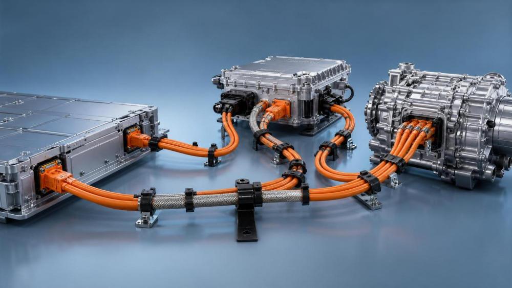
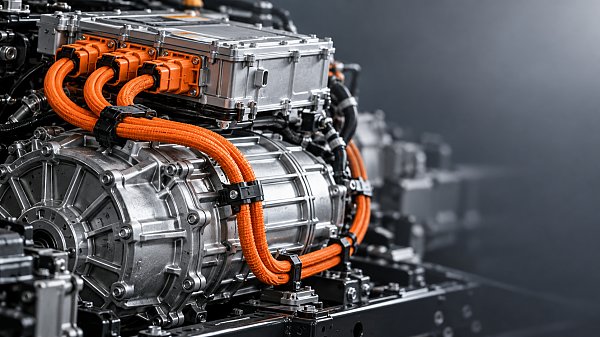
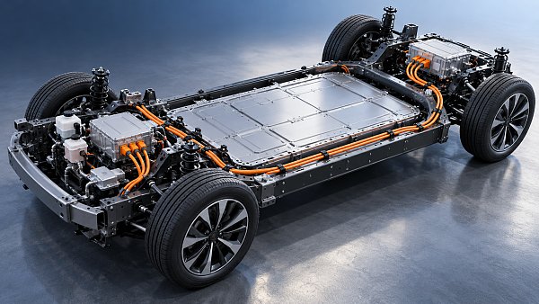
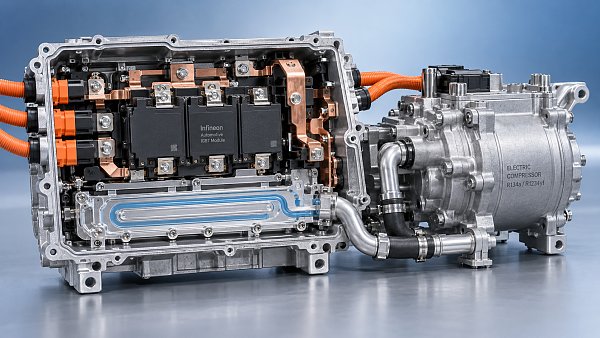
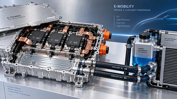
A high voltage wiring harness carries power between major electrical loads and energy sources. In battery electric and hybrid architectures, it often connects battery packs, power distribution units, drive motors, onboard chargers, DC/DC converters, and electric compressors.
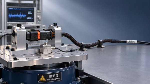
Simple cable sizing does not reflect the full engineering burden. The harness must survive vibration, thermal cycling, chemical exposure, moisture, assembly stress, and electromagnetic interference within a limited installation space.
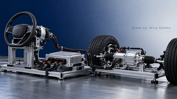
This broader view is increasingly relevant on platforms tracked by GACT, where wiring, thermal systems, steer-by-wire, smart cockpit electronics, and electric power components are becoming more interconnected.
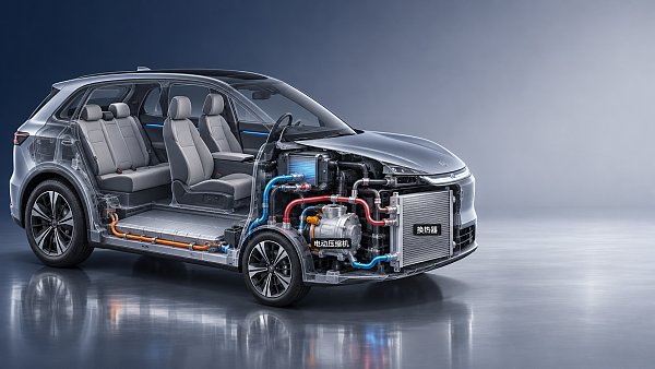
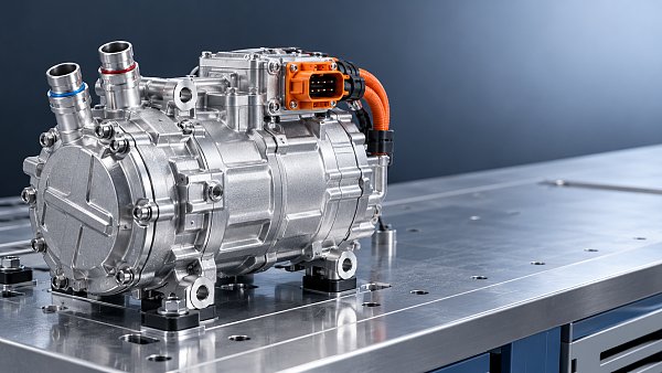
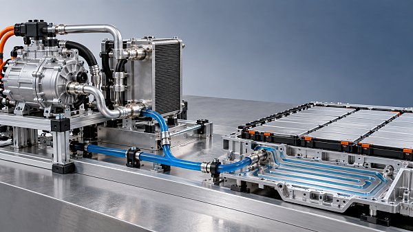
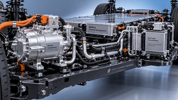
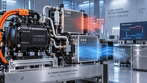
For example, battery liquid cooling systems and heat pump layouts can change local temperature zones. Electric compressors and data cables may share nearby routing paths. These interactions make the high voltage wiring harness a cross-functional design item rather than an isolated part.
The safety baseline starts with insulation and material stability
The first screening step is usually electrical insulation, but the real question is how insulation performs over time. Rated voltage must align with the platform architecture, yet aging behavior under heat, flexing, and contamination is equally important.
Material choice affects creepage resistance, abrasion tolerance, and dielectric durability. In underbody or battery-adjacent routes, the jacket may face stone impact, coolant exposure, road salt, and repeated temperature swings.
A technically acceptable harness on paper may still create risk if the insulation wall is too thin for the mechanical environment. Selection should therefore connect material data with the actual installation zone.
Points that deserve closer review
- Dielectric strength under operating and surge conditions
- Resistance to oil, coolant, humidity, and road contaminants
- Abrasion behavior near brackets, clips, and pass-through points
- Thermal aging margins at peak local temperatures
- Compliance with vehicle and regional safety standards
In practice, safety performance should be reviewed at harness level, not only cable level. Protective sleeves, grommets, sealing methods, and connector interfaces can change the real insulation outcome.
EMC performance is now part of harness quality
As vehicle electronics become denser, EMC is no longer a specialist concern handled late in development. A high voltage wiring harness can either support stable system behavior or become a source of noise coupling.
High-frequency switching from inverters, onboard chargers, and power conversion units increases the importance of shielding design, grounding continuity, and separation from communication lines.
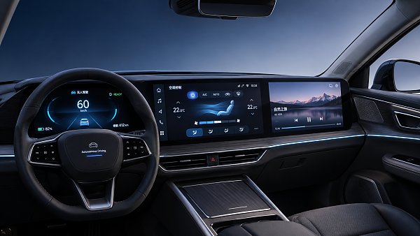
This is especially relevant in architectures that combine smart cockpit electronics, displays, HUD modules, and data cables with high-voltage power networks inside compact packaging spaces.
Typical EMC evaluation questions
A high voltage wiring harness with good EMC characteristics often reduces later troubleshooting costs. It also helps protect adjacent electronics from intermittent faults that are difficult to reproduce in field conditions.
Thermal exposure changes how routing should be judged
Heat is not only a material issue. It also affects route planning, clamp locations, bend recovery, sealing life, and connector retention force. This is why thermal mapping should influence harness selection early.
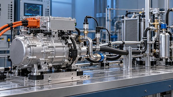
In many new energy vehicle layouts, the high voltage wiring harness passes close to battery enclosures, heat pump assemblies, e-compressors, coolant manifolds, and power electronics. Local hotspots can differ sharply within short distances.
A route that looks acceptable in a CAD model may become marginal when real operating temperatures are added. That gap often appears during endurance testing or after launch, when corrective changes are expensive.
Useful thermal review criteria
- Peak and continuous temperature near each segment
- Temperature rise from neighboring components
- Need for sleeves, barriers, or reflective protection
- Effect of heat on sealing and connector latch performance
- Impact of thermal cycling on fixation points
Connector reliability often decides field performance
Even when cable materials are well selected, failures frequently appear at the interface. Connectors carry the combined effects of current load, assembly variation, vibration, ingress risk, and maintenance activity.
For a high voltage wiring harness, connector selection should consider contact resistance stability, HVIL integration, sealing robustness, locking clarity, and tolerance to repeated mating where service access is expected.
Packaging also matters. Oversized connectors may complicate routing near battery packs or e-axles, while undersized designs can raise thermal stress or reduce handling safety during assembly.
In export-oriented programs, connector strategy also affects qualification planning. Regional requirements, supplier validation records, and aftersales support can influence risk more than unit price differences.
Routing design should balance safety, packaging, and serviceability
Routing is where many selection decisions become real. A high voltage wiring harness must fit the vehicle, but it also needs safe separation, predictable fixation, and accessible service paths.
Good routing avoids sharp edges, moving parts, and crush zones. It also respects minimum bend radius, connector extraction space, and the need to isolate high-voltage paths from low-voltage communication networks.
This becomes more complex in platforms integrating battery cooling, electric compressors, steering systems, and cockpit electronics. Space competition is real, especially in compact vehicle architectures.
A practical routing checklist
Usually, the best routing decision is not the shortest path. It is the path that preserves electrical integrity, thermal margin, assembly repeatability, and future maintainability at the same time.
How to compare options in a real sourcing or validation process
A structured comparison method helps separate attractive datasheets from genuinely suitable solutions. The high voltage wiring harness should be judged against the full vehicle context and not only against catalog specifications.
That means combining electrical data, route constraints, connector details, thermal maps, EMC expectations, and supplier process capability into one evaluation view.
Industry platforms such as GACT are useful here because harness selection is tied to adjacent systems. Thermal management trends, electric compressor adoption, data cable density, and high-voltage architecture changes can all shift what counts as an acceptable design.
- Start with operating voltage, current, and fault condition boundaries
- Overlay route, heat, vibration, and service constraints
- Check connector interfaces and shielding termination details
- Review validation evidence, not only nominal claims
- Compare lifecycle risk, not only unit cost
The next step is usually straightforward: define the installation scenario, map the main stress points, and build a shortlist around those realities. That approach leads to better high voltage wiring harness decisions than relying on rating tables alone.
Have questions about this sector analysis, or seeking best practices specific to your niche? Drop us a line below and let the senior consultants at GAC assist you.
“We respect your privacy. Your information is strictly confidential.”
Related News
- 00
0000-00
Can a smart cockpit platform support multiple displays? - 00
0000-00
How is automotive connector vibration resistance tested? - 00
0000-00
How heat pumps save energy in automotive cabin climate systems - 00
0000-00
Is an EV heat pump worth it for winter driving range? - 00
0000-00
When should you use 50-ohm coaxial cable instead of 75-ohm?
Weekly Insights
Stay ahead with our curated technology reports delivered every Monday.
Recommended News
 Can a smart cockpit platform support multiple displays?Can a smart cockpit platform support multiple displays? Explore key requirements for performance, safety, connectivity, and supplier evaluation.Author:Time:Nov 07, 2026
 How is automotive connector vibration resistance tested?Automotive connector vibration resistance testing reveals hidden contact failures. Explore test profiles, continuity monitoring and pass criteria.Author:Time:Nov 06, 2026
 How heat pumps save energy in automotive cabin climate systemsAutomotive Cabin Climate Systems energy saving starts with smarter heat pump design. Explore real-world efficiency, cold-weather trade-offs, and testing tips.Author:Time:Nov 05, 2026
 Is an EV heat pump worth it for winter driving range?Is a heat pump worth using in a cold-climate EV? Discover how it affects winter range, when it pays off, and what to check before buying.Author:Time:Nov 04, 2026
 When should you use 50-ohm coaxial cable instead of 75-ohm?Coaxial cable 50 ohm or 75 ohm? Learn when to use each, avoid impedance mismatches, and choose the right cable for reliable RF and video performance.Author:Time:Nov 03, 2026
 How to select a high temperature motor harness for an EVChoose the right high temperature motor harness for your EV. Compare thermal limits, current capacity, shielding, routing, and validation evidence.Author:Time:Nov 02, 2026
 How much does electric power steering replacement cost?Electric power steering price typically ranges from $1,000 to $3,000 for major replacements. Discover cost factors, repair options, and tips for comparing quotes.Author:Time:Nov 01, 2026
 How to size an EV A/C compressor for the required cooling capacitySize an EV A/C Compressor with confidence. Explore cooling loads, performance maps and power limits to select the right compressor for your vehicle.Author:Time:Oct 31, 2026
 How to choose the right pitch for an FPC board connectorFPC board connector pitch affects space, assembly and reliability. Learn how to compare options and select the best fit for your design.Author:Time:Oct 30, 2026
 How zonal design affects harness routing in high-voltage EV architecturesExplore high-voltage electrical architecture zonal design and its impact on EV harness routing. Discover key trade-offs in cable length, safety, thermal performance, and service access.Author:Time:Oct 29, 2026
 How tariffs affect costs in global automotive parts supply chainsNavigate tariffs in the global automotive parts trade supply chain. Learn to compare landed costs, manage duty exposure, and uncover smarter sourcing strategies to protect your margins.Author:Time:Oct 28, 2026
 How to assess vendor lock-in in a software-defined vehicle platformAssess Software-Defined Vehicle platform lock-in with practical tests for API portability, data access, update control, and exit costs. Learn how to choose a platform with a proven exit path.Author:Time:Oct 27, 2026
 How ISO 26262 guides functional safety in steer-by-wire systemsExplore steering systems functional safety through ISO 26262. Learn how hazard analysis, fault-tolerant design, and validation build a stronger steer-by-wire safety case.Author:Time:Oct 26, 2026
 How to evaluate a steering angle sensor manufacturer's accuracy claimsEvaluate steering angle sensor manufacturer accuracy claims with practical checks on calibration, latency, and test evidence. Compare suppliers confidently and avoid costly selection mistakes.Author:Time:Oct 25, 2026
 How to diagnose CAN bus faults in a hybrid vehicle control unitDiagnose Hybrid Vehicle Systems control unit CAN bus faults with step-by-step power, wiring, and waveform checks. Find the root cause and avoid unnecessary replacement.Author:Time:Oct 24, 2026
 How does battery cooling pipe diameter affect coolant pressure drop?Battery Cooling Pipe diameter affects coolant pressure drop and pump power. Explore sizing calculations and practical tips to optimize EV battery cooling and compare options with confidence.Author:Time:Oct 23, 2026
 How to assess PPAP readiness of automotive sensor system manufacturersAssess Automotive Sensor Systems manufacturers for PPAP readiness. Learn to verify production evidence, measurement capability, validation, and traceability to reduce sourcing risks.Author:Time:Oct 22, 2026
 What to ask an FPC connector manufacturer about reliability testingChoosing an FPC Connector manufacturer? Learn what to ask about reliability testing, failure limits, and traceable results to reduce design risks and select with confidence.Author:Time:Oct 21, 2026
 How to verify vehicle fitment for an aftermarket AC evaporatorNavigating the evaporator aftermarket? Verify vehicle fitment with VIN data, OE numbers, and physical interface checks. Use this guide to avoid costly mismatches and order confidently.Author:Time:Oct 20, 2026
 How electric compressor speed affects EV battery cooling capacityElectric compressor technology: battery cooling depends on more than RPM. Discover how speed, refrigerant flow, and system limits affect EV cooling capacity and energy efficiency.Author:Time:Oct 19, 2026
 How to verify a variable frequency compressor supplier’s efficiency claimsVerify a variable frequency compressor supplier’s efficiency claims using COP boundaries, matched test conditions, and duty-cycle data. Learn how to choose with confidence.Author:Time:Oct 18, 2026
 How bend radius affects FPC reliability in automotive camera modulesAutomotive FPC applications: camera module reliability starts with bend radius. Learn how stack-up, strain, and validation guide robust designs and help prevent costly failures.Author:Time:Oct 17, 2026
 How to diagnose intermittent loss of electric power steering assistMaster power steering system diagnostics to trace intermittent EPS assist loss. Learn proven checks for voltage, wiring, and fault codes to avoid costly guesswork.Author:Time:Oct 16, 2026
 How to size automotive power modules for electric compressorsSize automotive power modules for electric compressors with confidence. Learn how voltage, phase current, losses, and cooling shape reliable selection—and avoid costly oversizing.Author:Time:Oct 15, 2026
 Why automotive power electronics are shifting to silicon carbideAutomotive Power Electronics are shifting to silicon carbide. Discover how SiC can cut losses, boost EV power density, and reshape cooling, reliability, and system costs.Author:Time:Oct 14, 2026
 How EV adoption shapes the electrically driven compressor marketExplore how EV adoption shapes the electrically driven compressor market, from battery cooling and heat pumps to supplier margins. Discover the drivers of profitable growth.Author:Time:Oct 13, 2026
 How to size a PTC heater for reliable EV cabin heatingPTC Heater sizing for EV cabins: learn how to balance defrost performance, heat-pump integration, airflow, voltage range, and battery power for reliable winter comfort.Author:Time:Oct 12, 2026
 What determines the cooling output of electric automotive AC compressors?Automotive air conditioning compressors electric systems: explore how speed, voltage, refrigerant, controls, and heat exchangers shape EV cooling capacity and efficiency.Author:Time:Oct 11, 2026
 What makes a touchscreen media head unit responsive enough for daily use?Touchscreen media head unit performance explained: discover what delivers fast starts, smooth maps, reliable phone pairing, and responsive daily driving.Author:Time:Oct 10, 2026
 How Does a Battery Management System Communicate Cooling Demand?How does a battery management system communicate cooling demand? Explore CAN signals, thermal priorities, fault handling, and EV cooling control strategies.Author:Time:Oct 20, 2026