When to Use FAKRA Cable Assembly in ADAS and Infotainment Systems




Why FAKRA cable assembly decisions start with the vehicle scenario
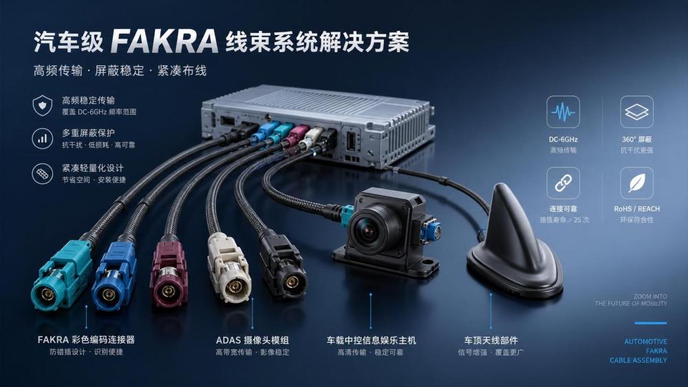
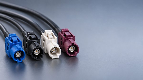
A FAKRA cable assembly is rarely selected by frequency alone.
In ADAS and infotainment systems, the real question is where the signal travels, how stable it must remain, and what packaging limits the vehicle architecture creates.
That is why the same FAKRA cable assembly may work well for a roof antenna path, yet become risky near a camera module, display stack, or mixed high-voltage routing zone.
In actual automotive programs, requirements split quickly between smart cockpit electronics, connectivity modules, radar, cameras, and evolving wiring harness layouts.
This matters even more as electrification and intelligent cabins push tighter packaging, longer data paths, and more interfaces into fewer zones.
For platforms tracking wiring, cockpit displays, media head units, and vehicle communication components, FAKRA cable assembly choices sit at the intersection of signal integrity, durability, and validation efficiency.
The practical value is straightforward.
A suitable FAKRA cable assembly reduces noise risk, supports predictable connector matching, and helps vehicle-level testing move faster across antenna, camera, display, and telematics functions.
Different vehicle functions create different cable priorities
The main reason scenarios differ is that ADAS and infotainment systems do not fail in the same way.
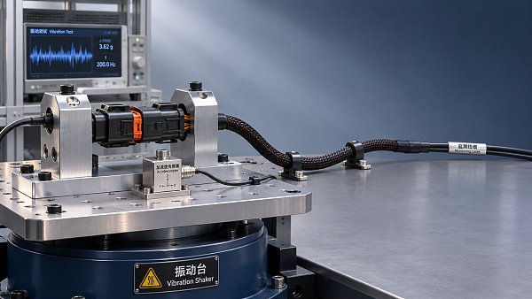
Radar and camera links are more sensitive to signal loss, shielding continuity, and connector locking under vibration.
Infotainment links often face denser routing, multiple interfaces, and stronger pressure on assembly flexibility inside the cockpit.
A roof antenna path may prioritize RF consistency over a longer route.
A rear camera path may care more about bend radius, moisture exposure, and stable insertion performance during service.
A head unit connection may require a FAKRA cable assembly that fits crowded spaces near displays, USB modules, and communication control units.
More vehicle architectures now combine smart cockpit electronics with lightweight harness design and higher electrical integration.
That shifts the selection logic from isolated connector specs to full-path compatibility, installation repeatability, and lifecycle robustness.
A quick view of what changes by scenario
Where ADAS usually justifies a FAKRA cable assembly
ADAS use cases often justify a FAKRA cable assembly when the signal path must remain predictable under heat, shock, and motion.
Front cameras, surround-view modules, radar sensors, and telematics units are common examples.
In these layouts, one weak connector interface can disturb system calibration, object detection reliability, or communication continuity.
A more useful judgment method is to look at failure consequences.
If signal interruption affects safety functions, driver assistance accuracy, or sensor fusion quality, the cable path deserves tighter control.
That is the point where a FAKRA cable assembly becomes less of a connector preference and more of a system reliability decision.
In practice, routing also changes the picture.
A short, protected camera link inside a sealed housing may tolerate a simpler configuration.
A longer path crossing body panels, harness branches, or mixed electrical zones usually benefits more from automotive-grade FAKRA control.
ADAS checks worth making before final selection
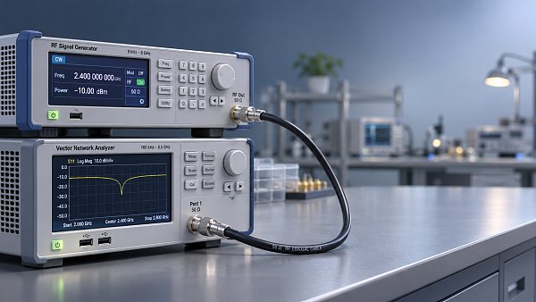
- Confirm the operating frequency and insertion loss target across the full route, not only at the connector face.
- Check whether nearby high-voltage harnesses or power electronics may raise EMI pressure.
- Review sealing, retention force, and vibration performance at the installed angle.
- Validate service access if the sensor module may require replacement during vehicle life.
Infotainment systems need FAKRA for different reasons
In infotainment, the trigger for using a FAKRA cable assembly is often integration complexity rather than pure environmental severity.
Media head units, cockpit displays, navigation antennas, and connected communication modules share limited installation space.
The challenge is not only transmission quality.
It is also avoiding assembly mistakes, maintaining connector identification, and preserving consistent signal behavior after repeated vehicle builds.
This is where a FAKRA cable assembly supports cleaner integration.
The keyed housing and standardized automotive use reduce the chance of mismatched connections across GNSS, LTE, radio, and other RF-related channels.
More advanced cockpit architectures add another layer.
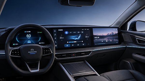
When displays, HUD systems, telematics, and central computing modules are packaged close together, cable routing must balance space, heat, and service loops.
A FAKRA cable assembly is often chosen because it simplifies that balance without treating the cockpit as a generic low-risk area.
What tends to matter more in cockpit applications
- Bend behavior behind displays and head units
- Connector identification during high-volume assembly
- Compatibility with mixed communication and power packaging
- Long-term fit after dashboard vibration and thermal cycling
The same connector logic does not apply across every harness zone
One common mistake is assuming that all RF or data-related links need the same FAKRA cable assembly design.
Vehicle zones behave differently.
Roof routing faces weather, body movement, and longer cable length.
Rear-view camera routing may face moisture, trim movement, and tighter bends.
Instrument panel routing tends to face dense packaging and thermal accumulation from nearby electronics.
Because of that, the right FAKRA cable assembly is linked to the harness zone, not only to the end device.
This is especially relevant in current vehicle platforms where lightweight wiring, zonal architectures, and higher functional integration are changing path layouts.
A cable assembly chosen early for a legacy path may no longer suit a new vehicle architecture with different branch lengths or interference exposure.
A simple comparison helps avoid overgeneralization
What gets misjudged before validation starts
The most frequent misjudgment is treating a FAKRA cable assembly as a catalog item with fixed value in every project.
That misses the vehicle-level context.
Another weak assumption is focusing on connector compatibility while ignoring route geometry, installation stress, or nearby power domains.
In electrified vehicles, mixed routing with high-voltage harnesses and thermal management packaging can quietly change interference risk.
It is also easy to underestimate service conditions.
A cable path that works in bench validation may become unreliable after trim removal, repeated connector handling, or seasonal thermal cycling.
Cost is another area where shortcuts cause trouble.
A lower initial cable cost can be offset by longer validation, more assembly errors, or difficult field replacement.
That is why FAKRA cable assembly decisions should include implementation cost, test time, and maintenance exposure, not only piece price.
A practical way to decide when FAKRA is the better fit
A FAKRA cable assembly is usually the better fit when three conditions appear together.
The signal path is high-frequency or RF-sensitive, the vehicle packaging is constrained, and connection reliability must hold across full automotive use conditions.
If only one of those conditions exists, the choice may need closer comparison with other interconnect options.
Before freezing the design, it helps to document several checks:
- Map the exact route from module to module, including branch points and service access.
- List electrical risks such as EMI sources, grounding behavior, and nearby high-voltage runs.
- Match connector keying, cable type, and retention needs to the actual installation process.
- Review regional validation expectations where the vehicle will be produced or exported.
This approach is useful across global programs because the same infotainment or ADAS concept may face different routing, climate, and compliance conditions in China, Europe, North America, or Southeast Asia.
The better decision usually comes from comparing application conditions first, then narrowing the FAKRA cable assembly specification around those conditions.
A clear next step is to sort vehicle use cases by signal criticality, route environment, and service exposure, then build a small scenario-based checklist for validation and sourcing review.
Have questions about this sector analysis, or seeking best practices specific to your niche? Drop us a line below and let the senior consultants at GAC assist you.
“We respect your privacy. Your information is strictly confidential.”
Related News
- 00
0000-00
What does each FAKRA cable color code mean? - 00
0000-00
How to compare noise ratings for battery coolant pumps - 00
0000-00
How bright should automotive display systems be in sunlight? - 00
0000-00
How heat pumps improve the efficiency of EV thermal systems - 00
0000-00
Can a smart cockpit platform support multiple displays?
Weekly Insights
Stay ahead with our curated technology reports delivered every Monday.
Recommended News
 What does each FAKRA cable color code mean?FAKRA cable color code explained: Explore common connector colors, typical uses and key compatibility checks before choosing a replacement.Author:Time:Nov 11, 2026
 How to compare noise ratings for battery coolant pumpsCompare coolant pump low noise ratings with confidence. Learn how test conditions, hydraulic duty, tonal noise and installation affect your choice.Author:Time:Nov 10, 2026
 How bright should automotive display systems be in sunlight?Automotive Display Systems need more than brightness to stay readable in sunlight. Discover why 1,000 nits is a starting point and how to evaluate glare and heat.Author:Time:Nov 09, 2026
 How heat pumps improve the efficiency of EV thermal systemsEV Thermal Systems use heat pumps to reduce heating energy demand. Explore how they work, where they excel, and what limits efficiency in cold weather.Author:Time:Nov 08, 2026
 Can a smart cockpit platform support multiple displays?Can a smart cockpit platform support multiple displays? Explore key requirements for performance, safety, connectivity, and supplier evaluation.Author:Time:Nov 07, 2026
 How is automotive connector vibration resistance tested?Automotive connector vibration resistance testing reveals hidden contact failures. Explore test profiles, continuity monitoring and pass criteria.Author:Time:Nov 06, 2026
 How heat pumps save energy in automotive cabin climate systemsAutomotive Cabin Climate Systems energy saving starts with smarter heat pump design. Explore real-world efficiency, cold-weather trade-offs, and testing tips.Author:Time:Nov 05, 2026
 Is an EV heat pump worth it for winter driving range?Is a heat pump worth using in a cold-climate EV? Discover how it affects winter range, when it pays off, and what to check before buying.Author:Time:Nov 04, 2026
 When should you use 50-ohm coaxial cable instead of 75-ohm?Coaxial cable 50 ohm or 75 ohm? Learn when to use each, avoid impedance mismatches, and choose the right cable for reliable RF and video performance.Author:Time:Nov 03, 2026
 How to select a high temperature motor harness for an EVChoose the right high temperature motor harness for your EV. Compare thermal limits, current capacity, shielding, routing, and validation evidence.Author:Time:Nov 02, 2026
 How much does electric power steering replacement cost?Electric power steering price typically ranges from $1,000 to $3,000 for major replacements. Discover cost factors, repair options, and tips for comparing quotes.Author:Time:Nov 01, 2026
 How to size an EV A/C compressor for the required cooling capacitySize an EV A/C Compressor with confidence. Explore cooling loads, performance maps and power limits to select the right compressor for your vehicle.Author:Time:Oct 31, 2026
 How to choose the right pitch for an FPC board connectorFPC board connector pitch affects space, assembly and reliability. Learn how to compare options and select the best fit for your design.Author:Time:Oct 30, 2026
 How zonal design affects harness routing in high-voltage EV architecturesExplore high-voltage electrical architecture zonal design and its impact on EV harness routing. Discover key trade-offs in cable length, safety, thermal performance, and service access.Author:Time:Oct 29, 2026
 How tariffs affect costs in global automotive parts supply chainsNavigate tariffs in the global automotive parts trade supply chain. Learn to compare landed costs, manage duty exposure, and uncover smarter sourcing strategies to protect your margins.Author:Time:Oct 28, 2026
 How to assess vendor lock-in in a software-defined vehicle platformAssess Software-Defined Vehicle platform lock-in with practical tests for API portability, data access, update control, and exit costs. Learn how to choose a platform with a proven exit path.Author:Time:Oct 27, 2026
 How ISO 26262 guides functional safety in steer-by-wire systemsExplore steering systems functional safety through ISO 26262. Learn how hazard analysis, fault-tolerant design, and validation build a stronger steer-by-wire safety case.Author:Time:Oct 26, 2026
 How to evaluate a steering angle sensor manufacturer's accuracy claimsEvaluate steering angle sensor manufacturer accuracy claims with practical checks on calibration, latency, and test evidence. Compare suppliers confidently and avoid costly selection mistakes.Author:Time:Oct 25, 2026
 How to diagnose CAN bus faults in a hybrid vehicle control unitDiagnose Hybrid Vehicle Systems control unit CAN bus faults with step-by-step power, wiring, and waveform checks. Find the root cause and avoid unnecessary replacement.Author:Time:Oct 24, 2026
 How does battery cooling pipe diameter affect coolant pressure drop?Battery Cooling Pipe diameter affects coolant pressure drop and pump power. Explore sizing calculations and practical tips to optimize EV battery cooling and compare options with confidence.Author:Time:Oct 23, 2026
 How to assess PPAP readiness of automotive sensor system manufacturersAssess Automotive Sensor Systems manufacturers for PPAP readiness. Learn to verify production evidence, measurement capability, validation, and traceability to reduce sourcing risks.Author:Time:Oct 22, 2026
 What to ask an FPC connector manufacturer about reliability testingChoosing an FPC Connector manufacturer? Learn what to ask about reliability testing, failure limits, and traceable results to reduce design risks and select with confidence.Author:Time:Oct 21, 2026
 How to verify vehicle fitment for an aftermarket AC evaporatorNavigating the evaporator aftermarket? Verify vehicle fitment with VIN data, OE numbers, and physical interface checks. Use this guide to avoid costly mismatches and order confidently.Author:Time:Oct 20, 2026
 How electric compressor speed affects EV battery cooling capacityElectric compressor technology: battery cooling depends on more than RPM. Discover how speed, refrigerant flow, and system limits affect EV cooling capacity and energy efficiency.Author:Time:Oct 19, 2026
 How to verify a variable frequency compressor supplier’s efficiency claimsVerify a variable frequency compressor supplier’s efficiency claims using COP boundaries, matched test conditions, and duty-cycle data. Learn how to choose with confidence.Author:Time:Oct 18, 2026
 How bend radius affects FPC reliability in automotive camera modulesAutomotive FPC applications: camera module reliability starts with bend radius. Learn how stack-up, strain, and validation guide robust designs and help prevent costly failures.Author:Time:Oct 17, 2026
 How to diagnose intermittent loss of electric power steering assistMaster power steering system diagnostics to trace intermittent EPS assist loss. Learn proven checks for voltage, wiring, and fault codes to avoid costly guesswork.Author:Time:Oct 16, 2026
 How to size automotive power modules for electric compressorsSize automotive power modules for electric compressors with confidence. Learn how voltage, phase current, losses, and cooling shape reliable selection—and avoid costly oversizing.Author:Time:Oct 15, 2026
 Why automotive power electronics are shifting to silicon carbideAutomotive Power Electronics are shifting to silicon carbide. Discover how SiC can cut losses, boost EV power density, and reshape cooling, reliability, and system costs.Author:Time:Oct 14, 2026
 How EV adoption shapes the electrically driven compressor marketExplore how EV adoption shapes the electrically driven compressor market, from battery cooling and heat pumps to supplier margins. Discover the drivers of profitable growth.Author:Time:Oct 13, 2026