How to Specify a CAN Bus Cable Assembly for Signal Integrity and EMI Control
A CAN network can look stable during bench testing and still become noisy, intermittent, or difficult to diagnose once it is routed through a real vehicle. This is a common problem when the CAN Bus Cable assembly is treated as a simple wire choice instead of a communication component with electrical, mechanical, and packaging consequences.
If you are comparing options for an EV thermal module, smart cockpit electronics, steering controls, or another distributed automotive subsystem, the wrong specification can lead to reflections, dropped messages, EMI complaints, connector mismatch, or avoidable redesign work. The practical question is not only which cable seems robust, but which CAN Bus Cable assembly actually matches the network speed, routing conditions, installation constraints, and long-term operating environment.
Why the specification stage often becomes harder than expected
Many teams start with a reasonable assumption: CAN is tolerant, widely used, and already proven in automotive applications, so the cable decision should be straightforward. In practice, selection gets complicated when several requirements collide at once. The assembly must carry differential signals cleanly, resist external noise, fit available connectors, survive vibration and temperature exposure, and still be practical for manufacturing and service.
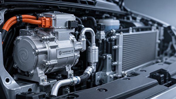
That is why problems often show up late. A design may appear correct on a schematic, but once the harness is bundled with power lines, routed through tight spaces, or installed near electric compressors, pumps, displays, motors, or high-voltage systems, the communication margin can shrink. This does not always produce a complete network failure. More often, it creates unstable behavior that wastes engineering time because the root cause is spread across signal integrity, EMI behavior, topology decisions, and harness construction details.
For technical evaluators making a selection decision, the useful approach is to treat the CAN Bus Cable assembly as part of the whole communication path rather than an isolated commodity item.
What usually goes wrong when a CAN Bus Cable assembly is underspecified
The most common issue is that teams focus on conductor size or outer durability first and leave characteristic impedance, twist consistency, shielding strategy, and termination interaction for later. That can work in a short, quiet setup, but it becomes risky in a vehicle where wiring paths and electromagnetic conditions are not clean or uniform.
Another frequent mistake is assuming that more shielding always means better performance. Shielding can help with EMI control, but it does not fix impedance mismatch, poor grounding strategy, bad splice execution, excessive stubs, or connector transitions that disturb the differential pair. In some layouts, a poorly implemented shield creates its own grounding complications and makes the assembly harder to integrate than a simpler, properly balanced cable design.
There is also a packaging trap. A cable may be electrically suitable but mechanically awkward. If the bend radius is too large, if the jacket is not matched to abrasion exposure, or if the connector backshell does not preserve pair geometry, the final installation may compromise the original specification. For systems in smart cockpit modules, steering column controls, battery thermal loops, and distributed sensor-actuator networks, that mismatch between electrical intent and physical implementation is a recurring source of trouble.
Start with the network, not the catalog
When choosing a CAN Bus Cable assembly, the first useful decision point is the network architecture itself. Before comparing material options, define the communication conditions the cable must support. That means checking the bus speed, total network length, expected node count, branch lengths, routing environment, connector interfaces, and whether the cable runs in a quiet low-power zone or near higher-noise circuits.
This matters because a cable that is acceptable for a short body-electronics link may not be the right fit for a longer harness path running through a mixed electrical environment. In the same way, a cable selected for a low-speed auxiliary module should not automatically be reused in a more noise-sensitive path just to simplify sourcing.
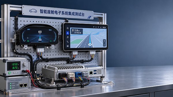
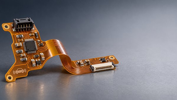
For evaluators working across automotive electronics categories, including data and communication cables, FPC-related interconnect areas, cockpit displays, head units, thermal control modules, and steer-by-wire adjacent architectures, a structured comparison usually saves time later. It helps separate true electrical requirements from assumptions inherited from another platform.
A practical checklist for specifying a CAN Bus Cable assembly
If the goal is selection rather than theory, it helps to move through the specification in a fixed order. The points below are where most good decisions are made or lost.
- Confirm the communication profile. Identify the CAN variant in use, the target bit rate, and the expected network length. Signal integrity decisions only make sense in relation to these basics.
- Define impedance expectations early. The differential pair geometry should support the network’s intended impedance behavior through the cable and through connector transitions. A good material choice cannot compensate for an unstable pair structure.
- Check conductor construction, not just gauge. Conductor size affects resistance, but strand design, flexibility, and installation stress also matter. In moving or vibration-prone zones, conductor construction influences durability as much as nominal electrical performance.
- Evaluate twist quality and consistency. Twist is central to common-mode noise rejection and balanced transmission. The detail to care about is not only whether the pair is twisted, but whether the geometry is maintained through the assembly process.
- Choose shielding based on the actual EMI environment. Use shielding when routing conditions justify it, especially near power electronics, electric drives, compressors, or dense electronic packaging. Do not assume the most heavily shielded design is automatically the best option.
- Review insulation and jacket materials against the installation zone. Temperature exposure, fluids, abrasion, and flexing conditions should shape material choice. A cable that is electrically correct but mechanically unfit will create reliability issues later.
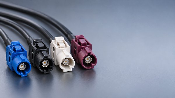
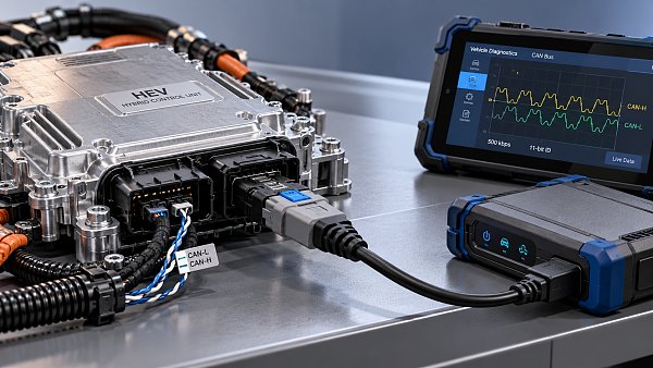
- Inspect connector compatibility as part of signal integrity. Connector selection is not only a mating and packaging issue. Terminal layout, strain relief, and pair handling at the termination point affect how well the assembly preserves the intended electrical behavior.
- Control branch and stub decisions. Even a well-selected cable can underperform if the network layout introduces excessive stubs or awkward branch routing. Harness architecture and cable specification need to be reviewed together.
- Plan grounding and shield termination deliberately. If shielding is used, specify how the shield is terminated and how that decision fits the grounding scheme. Vague instructions here often lead to inconsistent assembly execution.
- Check manufacturing repeatability. A specification that depends on perfect handling but is difficult to build consistently is a weak specification. The assembly must be manufacturable without losing pair integrity or termination quality.
How to compare unshielded, shielded, and more ruggedized options
One of the most common decision points is whether to stay with an unshielded twisted pair, move to a shielded design, or specify a more robust assembly built for harsher routing and environmental exposure. The right answer depends less on preference and more on where the cable lives and what surrounds it.
An unshielded twisted pair can be appropriate when the routing path is controlled, separation from noisy circuits is realistic, connectors maintain good pair geometry, and the network is not being pushed into a marginal condition. This approach can reduce weight, complexity, and cost pressure in some designs.
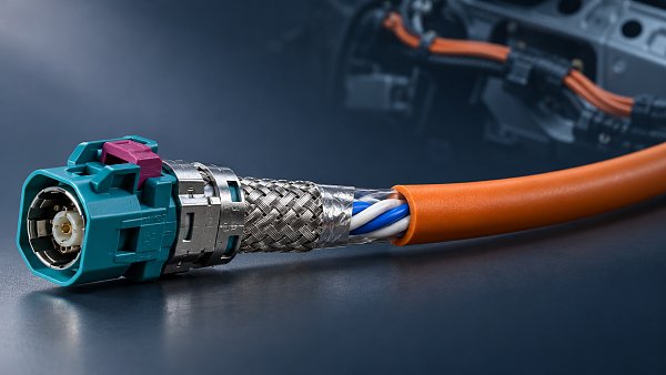
A shielded CAN Bus Cable assembly becomes more compelling when the cable shares space with stronger EMI sources, passes near switching devices, or must cross electrically busy zones where separation is limited. In those cases, shielding should be considered part of a broader EMI strategy that also includes routing discipline, grounding decisions, and connector treatment.
More ruggedized constructions are often justified in areas exposed to repeated movement, harsher temperatures, fluids, or mechanical wear. This is relevant in automotive systems where cable assemblies may be integrated near thermal management hardware, steering assemblies, under-dash packaging, or mixed signal-power harnesses. The main point is to avoid buying ruggedness that the application does not need while also avoiding a minimal design that creates future service issues.
Selection criteria that matter in real automotive packaging
In automotive programs, cable decisions are rarely made in an ideal lab layout. The assembly has to coexist with high-voltage harnesses, power distribution paths, display modules, ECUs, actuators, compressors, sensors, and increasingly dense vehicle electronics. That means the best specification is often the one that balances electrical margin with packaging realism.
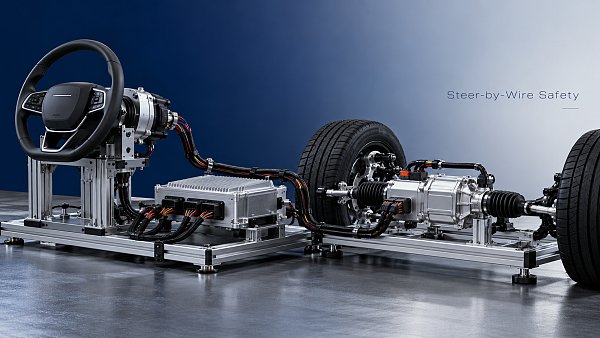
For example, if the cable is routed within a smart cockpit zone, flexibility, connector compactness, and routing control may matter as much as raw shielding coverage. If the cable is part of a thermal management subsystem with pumps, valves, or electrically active components nearby, environmental sealing and noise exposure become more important. If the network interfaces with steering-related electronics or other safety-relevant controls, consistency and diagnostic stability take priority over a minimum-material approach.
This is where broader market intelligence can help. Platforms such as GACT, which track automotive wiring harnesses, data and communication cables, thermal systems, cockpit electronics, and related component trends, are useful not because they replace engineering validation, but because they help evaluators compare how product categories, packaging constraints, and application scenarios interact across different vehicle architectures.
Common evaluation mistakes before final approval
Even when a cable assembly appears to satisfy the spec sheet, some approval mistakes still repeat across teams. One is validating the cable in isolation without checking the complete path through connectors, branch points, clamps, shields, and installation bends. Another is testing in a cleaner environment than the actual vehicle layout. Both can lead to overconfidence.
A third mistake is treating EMI and signal integrity as separate topics. In a real harness, they influence each other. A routing change made for mechanical convenience may alter coupling exposure. A shielding change made for EMI control may affect termination detail or packaging space. A connector swap made for sourcing reasons may disturb pair continuity. These are not separate procurement boxes; they are linked design choices.
Finally, teams sometimes approve a CAN Bus Cable assembly based on general automotive suitability without clearly documenting the intended topology, shield termination method, connector part family, and installation rules. That leaves too much room for variation between prototype, pilot build, and full production.
Common Questions
Is shielded cable always required for CAN communication in vehicles?
No. A shielded CAN Bus Cable assembly is useful in higher-noise environments or where routing separation is limited, but it is not automatically required in every application. Pair balance, impedance control, termination quality, and topology are still core factors.
What should I review first when comparing two CAN cable assemblies?
Start with network speed, total bus length, routing environment, connector compatibility, and how well each assembly preserves differential pair geometry. Those points usually tell you more than a basic material summary.
Can a good cable fix a poor CAN network layout?
Only to a limited extent. A better cable can improve margin, but it cannot fully correct excessive stubs, poor termination practice, bad grounding, or connector transitions that disturb the signal path.
How important is the connector in CAN Bus Cable assembly selection?
Very important. The connector affects pair handling, strain relief, shielding continuity where applicable, and the final transition from cable to ECU or module. A strong cable choice can be undermined by a weak termination design.
Should the same CAN cable specification be reused across every subsystem?
Not automatically. Reuse can simplify sourcing, but different subsystems may have different routing, thermal exposure, flexibility, and EMI conditions. Standardization is useful only when the application requirements genuinely align.
Making the final decision
The most reliable way to specify a CAN Bus Cable assembly is to work from the network outward: define the communication conditions, study the routing environment, match the cable structure to EMI and mechanical demands, and then verify that connectors and assembly methods preserve the intended signal path. That keeps the selection grounded in actual use rather than generic preference.
For engineers, product managers, and procurement teams evaluating automotive communication cables, a good decision is usually the one that avoids both extremes: neither an oversimplified wire choice nor a heavily built assembly with no clear application need. A disciplined comparison against topology, installation, and interference conditions is what leads to stable communication and fewer surprises later in the program.